The Bus is Leaving the Terminal
Using terminals with SOLIDWORKS Electrical works great when using traditional terminals that take one wire as an input and one wire as an output, possibly with multiple sets of circuits, such as these:
But how do you work with bus bars that are just glorified chunks of metal that you will solder, screw, or weld connections to?
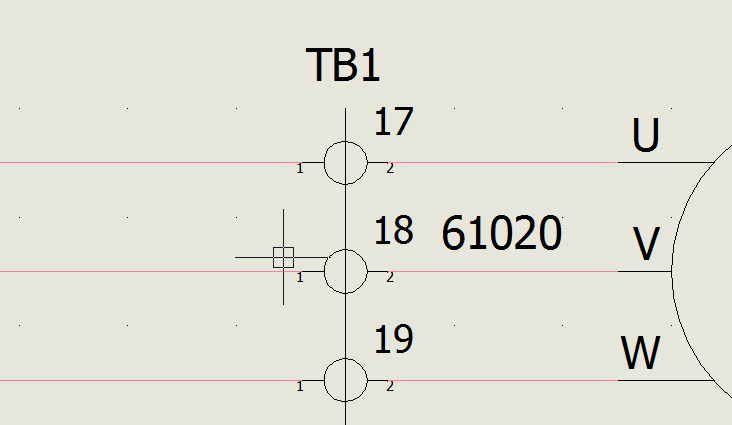
Take the following circuit
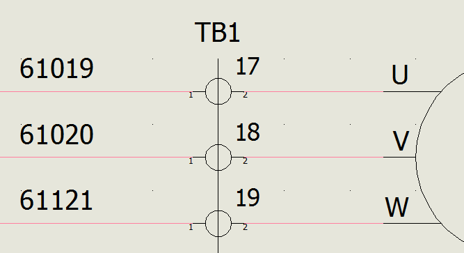
Those are individual terminals, as a part of Terminal Block 1. On the right side of the terminal block, because they are “passing” type circuits, the equipotential number is the same as the left, but each terminal mark still gets its own equipotential. So in this picture we have six wires, but three equipotentials.
But if TB1 was in actuality a bus bar, we would want 6 wires and only 1 equipotential. I could, of course, open the terminal strip and create bridges between terminals 17 through 19 to achieve that.
The only problem with that is the BOM will still show this as three separate components when TB1 is just one piece.
The reason that the circuit I showed will have multiple items in the BOM is that it treats each mark (17,18,19 above) as an individual piece of the terminal block.
So how do we represent a bus? There are a couple ways.
We will still utilize the terminal command, but will take advantage of the multi-level capability, tweaking it until it acts just like a bus.
When we create multi-level terminals, each level is an individual circuit on one BOM item. It assumes we are creating a schematic representation of this physical component:
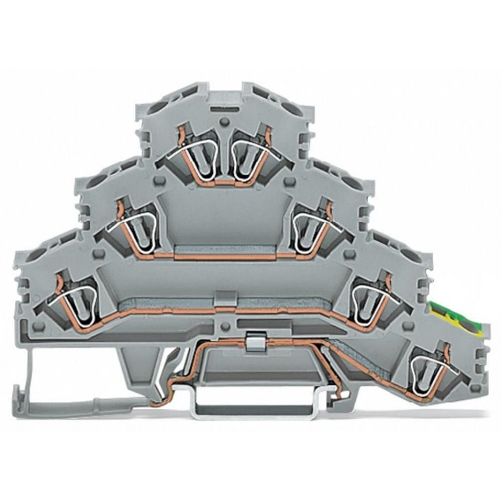
You can see that there are 3 circuits and a ground connection. First thing I’m going to do is create my bus, represented as a multi-level terminal, in my manufacturer parts library.
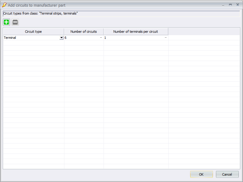
First, go into your manufacturer parts manager and create a new part in the terminal strips class. Put in the relevant information for your bus. Then, on the circuits tab, add multiple…
If there are 10 screws to attach wires, add 10 circuits. If it is just a bar that you are welding/soldering to, and don’t know how many wires you are attaching, then just create what you think is more than enough. For my example I am going to add 6 circuits. Only add 1 terminal per circuit. I’m assuming you actually won’t be using the symbol like we do for regular terminals, with a wire coming in on the left, and out on the right.
Select ‘OK’ and highlight all the circuits in the top portion of the circuits tab so you can edit the marks for each in the lower portion
Make sure everything you need to have filled out in the properties tab is filled out, and hit OK to finish creating the part.
Now is where the two ways to work with busses diverge. Method 1 is I could just use the terminal blocks like normal terminals, and then specify bridges to link the equipotentials. It would turn out just like we saw earlier in Picture 2, except I have now solved the extra items in the BOM problem. But I don’t feel like defining bridges all the time. I want to just place a symbol and be done. So that takes us to method 2…
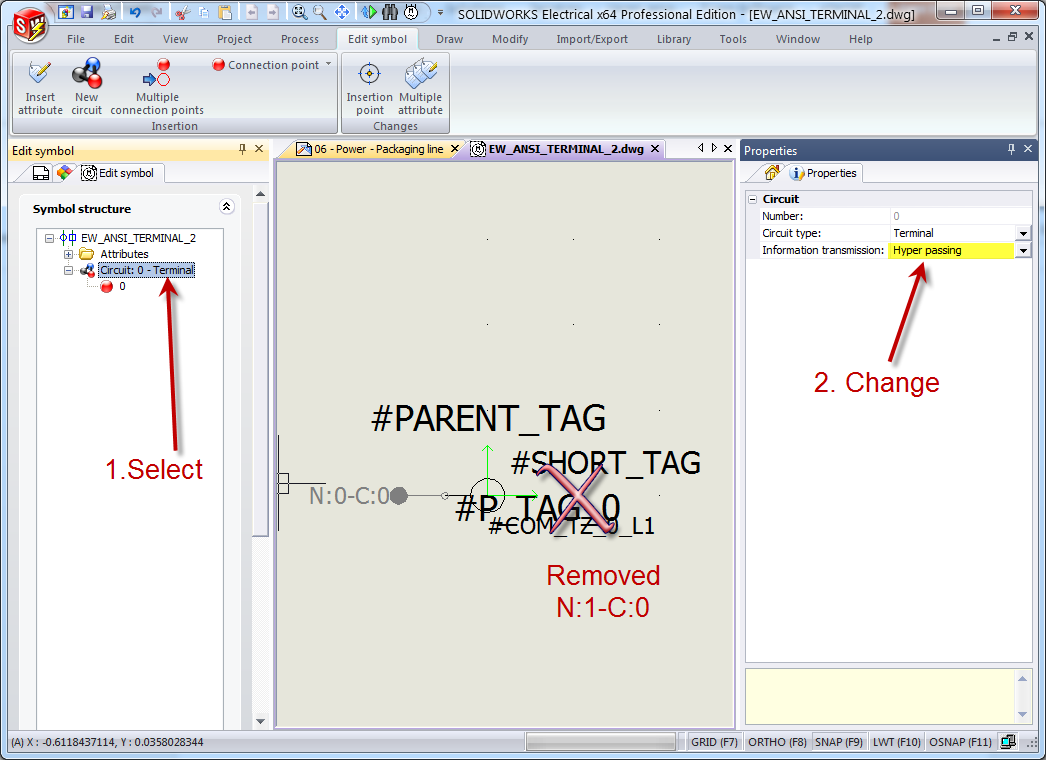
Now you need to create the symbol you will use. I created a copy of the standard terminal symbol, and edited the copy, deleting the right-hand side line and connection N:1-C:0. I also changed the circuit transmission type from ‘passing’ to ‘hyper passing’. Don’t forget to change the name of the symbol to something descriptive. I creatively called mine “HyperPassing Terminal.”
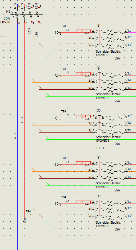
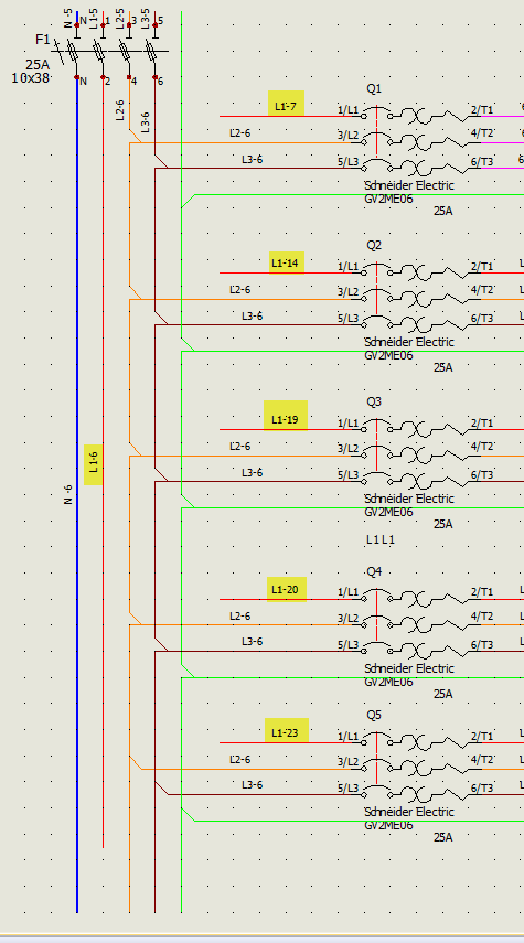
I want to connect the Phase 1 wires in the circuit below via bus bar. You can see that currently they are each different equipotentials.
From the schematic tab, ‘Insert terminal’ and select the new symbol you created. Place the terminal on the first wire. You will have to play around with the clicking to get the hang of the direction to place it. I found it best to rotate it before placing using right-click (rather than relying on the auto-rotate), then placing it on the wire and selecting the orientation with the arrow on the component side.
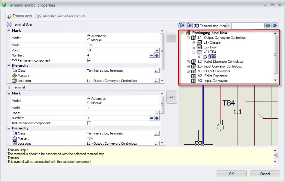
Once you place it, the terminal symbol properties window will appear. Let it create a new terminal strip (at least for the first symbol you place), and on the ‘Manufacturer part and circuits’ tab search for and apply the part you created. When placing the subsequent symbols, associate with the terminal that was created on the first placement by expanding the terminal on the right and selecting mark 1. It will label each symbol as 1.1, 1.2, etc.
Here is my example post-placement. I manually told it to show the equipotential numbers for the wires on the circuit breakers so you could see that it updated the equipotential. If yours haven’t changed at this point, it could be because you didn’t change the circuit type to hyper-passing. You can go back into the symbol and change it, then right-click on the symbol in the circuit to tell it to update. Or if your heart is set on passing, you can open your terminal strip and apply bridges.