SOLIDWORKS Flow Parameter Definition “TRANSFERRED”
SOLIDWORKS Flow Simulation is a CFD tool that manages a variety of fluid flow analysis. Transient, Steady State, Thermal, Internal, External, and so on. When you combine various aspects of these analysis, like time dependency of a periodic load, and varying thermal constraints over the same period the project starts to become complicated. Do not worry, SOLIDWORKS Flow Simulation has you covered with the Flow Parameter Definition “Transferred” option.
Let us look at the setup for the model. We have a series of periodic loads that are applied in real life over 24 hours. These loads vary in duration as well as temperature depending on the time at which the loading is applied, during that 24-hour window.
For example, the load is periodic and turns on and off at a set time of 101 seconds on, and 6 seconds off. The load is applied at the first hour at 450 degrees C. For the second hour 50 degrees C, and 650 degrees C and so on.
To create a manual time curve to define this series of events would be tedious. It is better to use the periodic application of the load and divide the overall 24 hours of real time run into multiple projects at given temperatures. We can divide the 24 hours into sections by transferring the boundary conditions as an initial condition in the subsequent run.
To apply the periodic load, go to your heat source (or given boundary condition) and choose dependency. Dependency allows the user to adjust the loading via a time, goal, or parameter dependency. In this case we will use time and add the time curve to reflect 101 seconds on and 6 seconds off. Choosing periodic repeats this cycle.
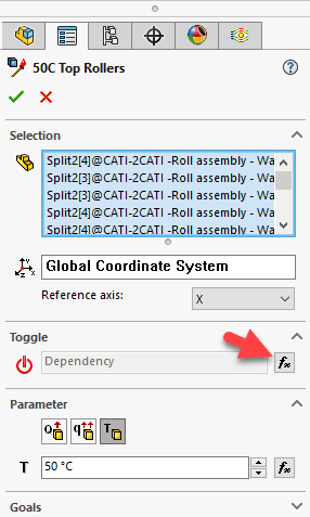
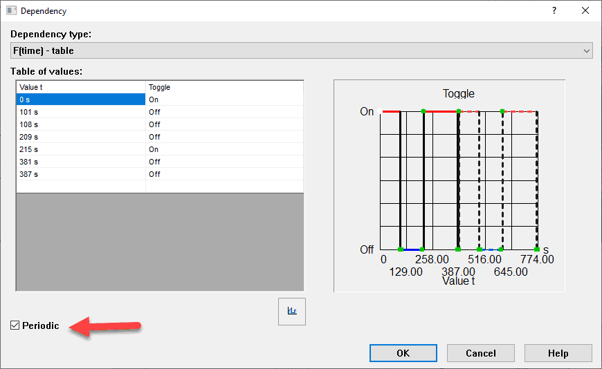
In this case the heat source is 50 degrees C for 1 hour. Doing the overall 24 hours in a set of stages per hour allows the user to vary the temperature and reuse the periodic loading. Run the first hour project to completion. Clone the project naming it per the second loading condition. Edit and adjust the heat source (or boundary condition you want to vary) and change it to the new temperature.
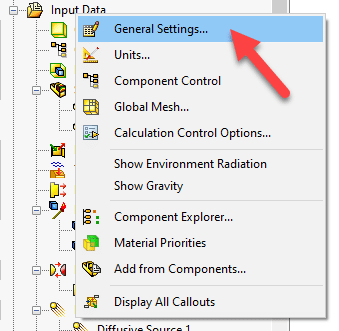
The next step is crucial to continue the run from the end of the first study. Edit the General Settings by right mouse button on the “Input Data” folder and choose General Settings.
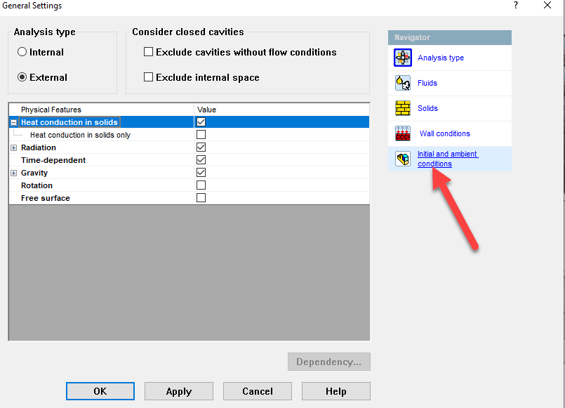
Go to the “Initial and ambient conditions” section
At the pull down to the right of Parameter Definition choose “Transferred”
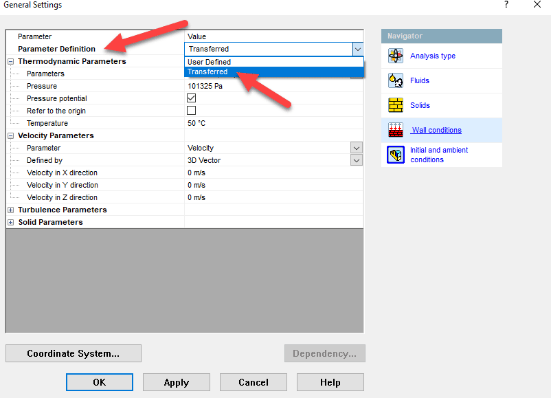
Browse to the previous study. And choose OK
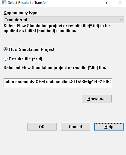
This simple pull down allows the user to start the new subsequent study from the previous studies ending thermal, velocity, and pressure mapping. These two SOLIDWORKS Flow Simulation options, Periodic loading, and Transferred Flow parameters allow a user to setup and run a long duration set of studies with varying inputs over time.
For more information reach out to your friendly CATI account manager. Check out the CATI YouTube page, and additional Simulation Blogs on the CATI blog.
Robert Warren
Simulation Specialist, Elite Application Engineer
Computer Aided Technology

 Blog
Blog 