SOLIDWORKS Electrical: Handling Multi-Part Components
I was recently working with a SOLIDWORKS Electrical project that a customer had developed, and I ran across a situation that I see quite often. Users that develop components that are made up of multiple parts, often run into issues when associating symbols to them in SOLIDWORKS Electrical Schematic.
Often the problem goes unnoticed until the project is moved to SOLIDWORKS CAD using the Electrical 3D add-in and the wires and cables are routed. Generally, the routing analysis will display an error having to do with the connection points.
In this blog I’m going to show an example where this can easily happen and a way to spot the issue and fix it before entering the CAD environment.
We want to create a part that allows us to connect two ring terminals together mechanically AND electrically. The model in question will look like this:
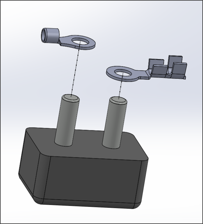
This component will be made up of 3 separate parts:
- Ring terminal 1
- Ring terminal 2
- Connection block 3
Easy Enough.
The symbol will have one circuit with two terminals. One for each ring terminal:
So far so good.
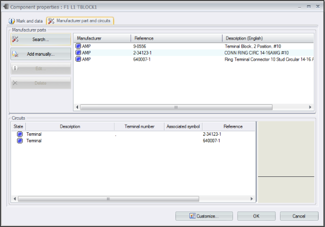
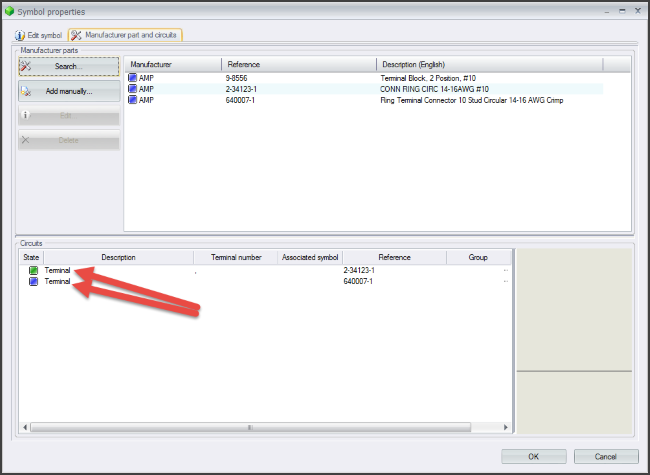
Now we add a connector to the project and mark it TBLOCK1. To TBLOCK 1 we add the already existing MFG parts:
- Terminal 1: 2-34123-1
- Terminal 2: 640007-1
- Connection Block: 9-8556
We have two terminals which will work with our symbol which also has two terminals.
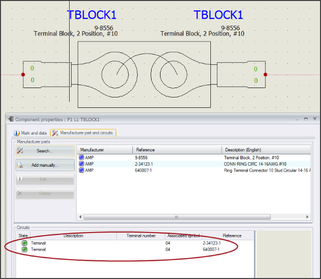
The problem happens when we associate the symbol to component TBLOCK1.
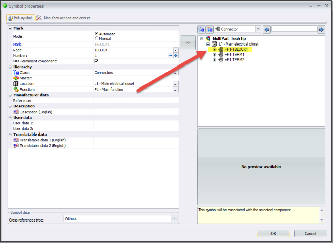
Because we added two terminal that are usually used in isolation, they each have a terminal but both connection points are circuit 0, terminal 0 (or to SOLIDWORKS fan boys: 0_0).
When we associate the symbol to the component, only ONE symbol terminal will associate to the component due to this mismatch.
If you are paying close attention, you will notice that one of the symbol terminals is connecting to the terminal in the first ring terminal but the second one is not associating to the second ring terminal. Again, that’s because each terminal MFG part has a connection part of 0_0 but the symbol has two terminal of 0_0 and 0_1.
So how can we fix this? Well, we can’t have a symbol with two connection points of 0_0 so that’s out. Two solutions come to mind:
- Create a new component with a single circuit having two terminals (0 and 1). This will also require possibly creating an assembly of the SOLIDWORKS parts and re-assigning one of the terminal CPoints to the second terminal (0_1)
- Have the symbol(s) more closely match the architecture of the component. Namely, use two separate ring terminal symbols.
I’m going to suggest the latter for the following reasons:
- – We would like to re-use existing parts without having to create new ones.
- – By keeping the symbols/components as generic as possible, we can easily replace the existing terminals without having to again, make a new component.
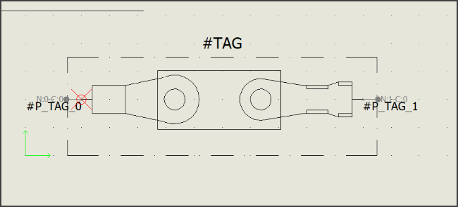
So by using existing generic symbols, we solve the problem and keep things generic so that if we need to change either the symbol or the Mfg. parts, we can easily do that. I simply draw a rectangle around the terminals to show that it is part of a block.