SOLIDWORKS: How to Insert a Printed Circuit Board
As I was walking around town recently, I noticed a woman pushing a baby stroller that had USB ports. Her phone was plugged into one and a travel mug was plugged into another. It occurred to me that so many things today are designed with a printed circuit board, even something like a baby stroller.
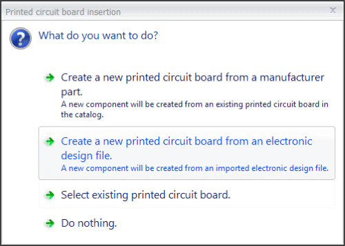
Designers today have to consider not only the aesthetics of products, but how to integrate all the electronics that go with it. Trying to document that integration can be challenging without the proper tools. When you select the “Insert Printed Circuit Board” icon in SOLIDWORKS Electrical, you are given four options. Keep reading to find out what each of those options mean.
SOLIDWORKS Electrical Schematic Professional has tools to help Electrical Engineers document a printed circuit board within the overall electrical design. One of those tools is Printed Circuit Boards. Once the icon has been selected, this window will appear showing four clickable options.
Option 1
Option 1 will create a new PCB component within your project from an existing PCB within your library.
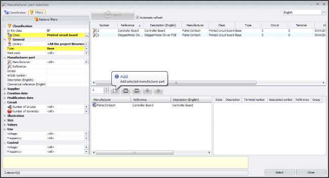
All you have to do is select the symbol to represent the PCB, and you’re done.
Option 2
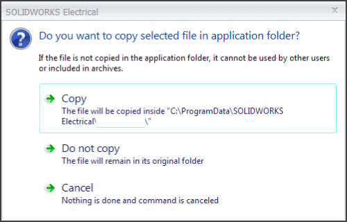
The second option you can choose will create a new PCB component with a new manufacturer part within your project from an existing IDF (Intermediate Data Format) 2 or IDF 3 file (.emn). When selecting this option, you are asked if you want to copy the IDF file to the project. Copying the file will give other users access to the IDF file within the project, as well as include it during a project archive.
After you decide whether or not to copy the IDF file, you are them prompted to enter any additional properties, circuits, or terminals you wish to be a part of your PCB.
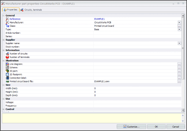
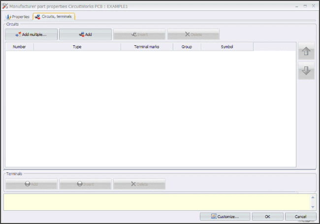
You then just need to select a symbol to represent the PCB, and you’re done.
Option 3
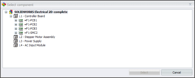
Option 3 gives you the ability to select an existing PBC within your project and duplicate it.
Option 4
Do nothing. Select this option if you are ready to exit out of the Insert Printed Circuit Board command.
For those who have SOLIDWORKS Electrical 3D, when inserting a PCB component that has no reference to a 3D model, selecting option 2 (above) will also display this dialog.
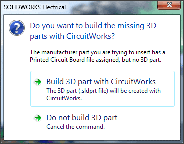
CircuitWorks is part of SOLIDWORKS Professional and Premium. Selecting the option to Build 3D part with CircuitWorks will build the PCB using the associated IDF file and open it within the assembly file you are in. Position it like any other component within SOLIDWORKS.