SOLIDWORKS: Modeling Gears for Assemblies
Modeling Gears for SOLIDWORKS Assemblies
The next component I want to take a look at in our discussion of files that slow down SOLIWORKS assembly performance is the gear. Gears are used in a lot of mechanical designs, and are often parts that are downloaded from the web and inserted directly into our assemblies.
There is a time and a place for detail. Having highly detailed parts for piece part manufacturing is perfectly acceptable and necessary. Placing highly detailed parts into large assemblies can cause severe performance issues.
Let’s take a look at a typical imported gear file.
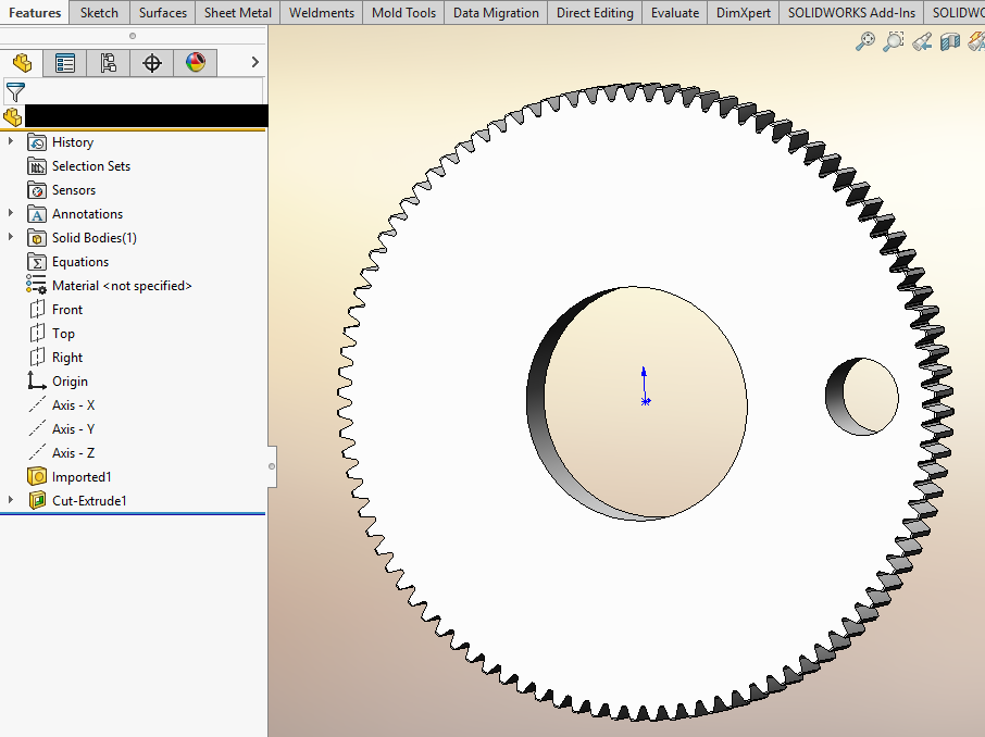
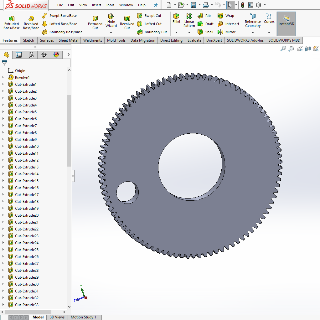
Taking a look at the part, it is imported geometry and there is an extra hole cut into the gear.
I took a look at the performance evaluation data for this file and it shows us that all the rebuild time is in the cut hole.
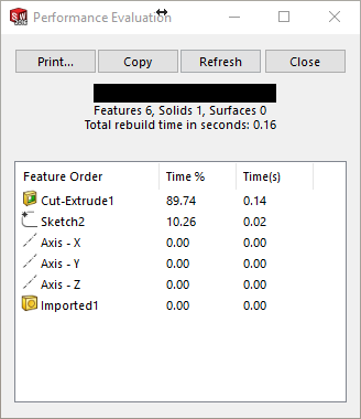
Our initial file size is 1684 MB
But our Graphical triangles to display this is 19190
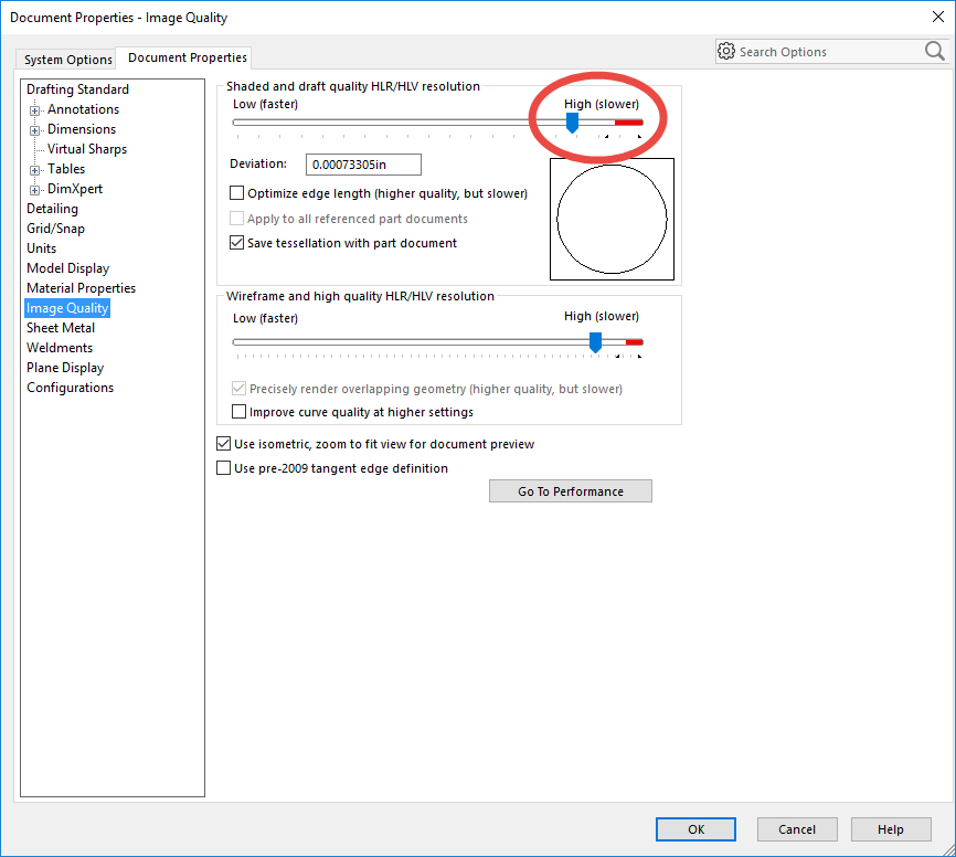
We also want to take a look at the image quality. The slider should be between ¼ and ½ of the way from the left side. Moving the slider to the right end (Red Zone) will cause exponential file size growth. This is an imported part, so the template that was used when imported had the image quality set very high.
If the file size is not very large and triangle counts do not seem excessive, how do we improve the performance of this part? Keep in mind that we usually never have only one gear in an assembly. When you look at the performance impact a part has on an assembly you have to multiply it by the number of instances in the assembly.
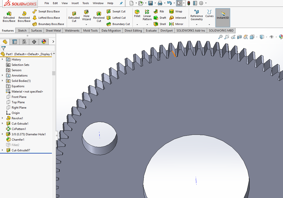
I ran a feature recognition on the file. SOLIDWORKS was able to recognize all of the geometry and convert it to parametric features.
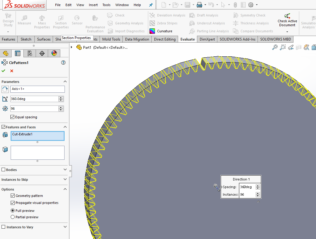
The file contains 96 cut extrudes for all of the teeth (96 tooth gear). I deleted 95 of the cut extrude features and replaced them with a circular pattern. In the pattern options, I set the geometry pattern option to simplify the geometry and improve the rebuild time.
After adding the tooth pattern back in, I was able to recreate the fillet feature. By having the fillet feature as its own parametric feature, this allows me to suppress the feature in my large assembly. When you place multiple gears into an assembly we often do not need to see the small details such as the fillets.
Our initial file size is 1684 MB with 19190 graphical triangles. The new file size is 464 MB with 3304 graphical triangles. This is a 72.4% file size reduction and an 82.7% reduction in the graphical triangle counts.
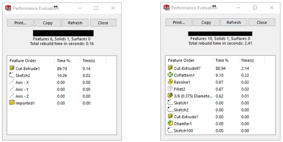
There is a little trade-off with this file. From the 2 images above, we can see that the total rebuild has actually increased due to adding all the parametric features, but we have significantly reduced the file size and more importantly dramatically reduced the graphic triangle count. The reduced triangle count will have the biggest impact on a large assembly.
Keep in mind that we can use configurations to help us preserve the full detail of the part for the individual part drawings, and we can use a simplified configuration in the assembly for performance.
The more files we can simplify, the better your assemblies will function.
Hope this helps.
Bryan Pawlak
Sr. Application Engineer
Computer Aided Technology