SOLIDWORKS 2018 What’s New – Export Deformed Geometry – #SW2018
SOLIDWORKS 2018 What’s New – Export Deformed Geometry – #SW2018
SOLIDWORKS Plastics is a manufacturability analysis tool, that provides the designer insight into the injection process of their part. Flow, Pack, Cool and Warp are at the designer’s fingertips giving an understanding of the entire injection molded process.
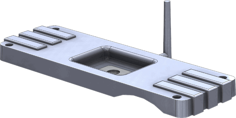
One of the features that SOLIDWORKS Plastics offers is the ability to export deformed geometry. At the end of the injection mold process the part is released from the mold. Due to in molded stress, cooling rates, gravity, and geometry the part can warp. This warp is depicted by Plastics, and will allow the user to export the deformed, or warped result. This is useful when checking the warped result versus nominal clearance in an assembly.
The warped geometry can also be exported as a counter deformed state. This allows the mold to be created so that when warp occurs the part will deform back to nominal dimensions.

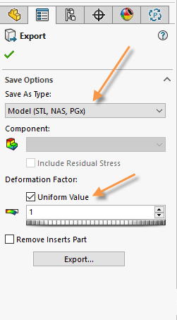
Previously Plastics 2017 and older the export result allowed for a uniform scale factor. Because the part can warp differently in all three directions, SOLIDWORKS 2018 added the ability to apply a different scale factors to the X,Y, and Z directions. This give more control to the designer, and adds precision to the mold making process.
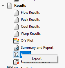
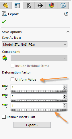
The export Deformed Geometry option is available after a warp analysis has been completed. Right mouse button on the Export folder in the Plastics’ design tree.
Select the export type. Uncheck the Uniform Value option to change the Deformation factor for each direction.
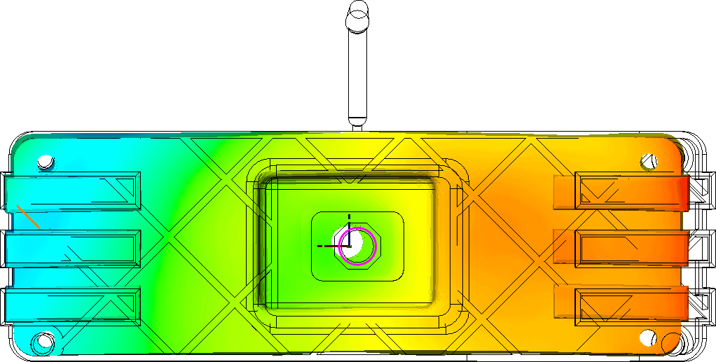
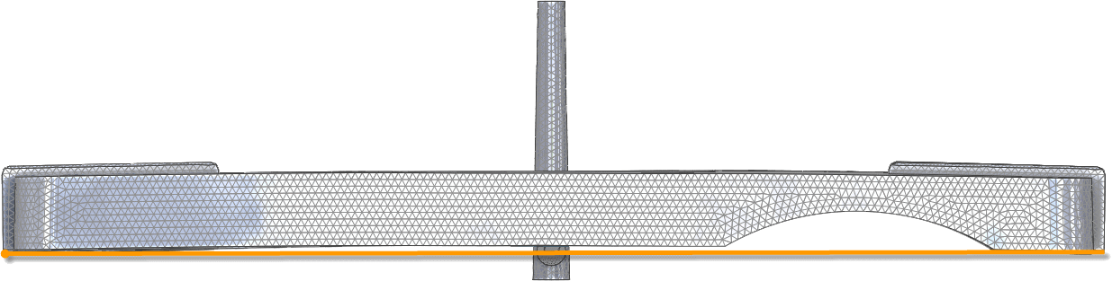
A value of -1 produces the counter deformed version. The part has been exported in a counter deformed shape in the Y direction as shown below. Note that the orange line shows the nominal design.
I hope this part of the What’s New series gives you a better understanding of the new features and functions of SOLIDWORKS 2018. Please check back to the CATI Blog as the CATI Application Engineers will continue to break down many of the new items in SOLIDWORKS 2018. All of these articles will be stored in the category of “SOLIDWORKS What’s New.” You can also learn more about SOLIDWORKS 2018 by clicking on the image below to register for one of CATI’s Design Innovation Summits.
Robert Warren
Simulation Specialist