SOLIDWORKS Configurations Part 1: Basics and Creating Configurations
SOLIDWORKS configurations allow users to maintain multiple versions of a part or an assembly in a single file. The differences between configurations are established by changing dimension values, suppressing features, and changing other parameters. (For a full list of configurable items, see the SOLIDWORKS Help article, “Configurable Items for Parts”).
This blog is the first part in a series about configurations. In this article, we will examine the best cases for using configurations in SOLIDWORKS, preparing a model for configuration, and 3 methods for creating configurations: manually, using a Configuration Table, and using a Design Table. Future articles in this series will cover using configurations in assemblies and using configurations in drawings.
Why Use Configurations in SOLIDWORKS?
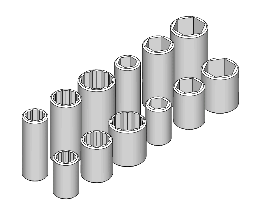
The most common reason to use configurations is to quickly establish a family of similar parts or assemblies. In the image above, all twelve sockets are contained in a single part file. By assigning different values to the outer diameter and depth of the socket and choosing whether to use a 12-point cut or a 16-point cut, we can easily create multiple configurations of the socket without having to go through the work of recreating all the sketches and features that make up the model. In this way, configurations allow for easy propagation of design changes.
Configurations are also commonly used to create simplified versions of parts for use in assemblies and analysis. For example, it is common to suppress features that are largely cosmetic and computationally heavy—such as threads or fillets—when using a part in a large assembly or running a simulation. Configurations can also be employed to describe a model as it proceeds through steps in the manufacturing or assembly process.
Preparing a Model for Configuration
Since configuring a model often involves changing the values of dimensions and suppressing features, it is good practice to change dimension and feature names to simplify the configuration creation process.
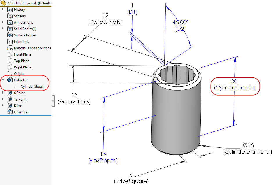
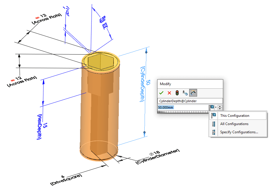
For the socket model, we changed the name of several dimensions to more clearly represent what the specific dimensions control. This way, when we change a dimension between configurations, we can make sure we know what the dimension is controlling. Dimensions can be renamed by selecting the dimension and changing the name in the Property Manager, or by double-clicking on a dimension and changing the name from the Modify dialog.
We also changed the name of several features, to make it easy to choose which ones will remain unsuppressed down the line. Features can be renamed by slow double-clicking on the feature name in the Design Tree.
Global variables and linked dimensions are also very helpful for creating configurations. By creating and assigning global variables, we can control multiple dimensions in one step. Linking dimensions similarly ensures that dimensions that should be equal will update together, reducing the number of dimensions that need to be changed between configurations. For more information on creating Global Variables, please see SOLIDWORKS: Managing your design using Global Variables and Equations by Roger Ruffin.
Creating Configurations Manually
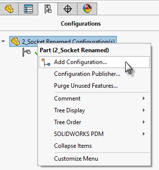
Every SOLIDWORKS part or assembly model starts off with a default configuration, and there are multiple methods for creating additional configurations. The first is to manually specify new configurations from the ConfigurationManager tab of the FeatureManager. Right clicking on the top-level part or assembly in the ConfigurationManager (or right clicking neutral space) and choosing “Add Configuration…” will start the Configuration Properties command.
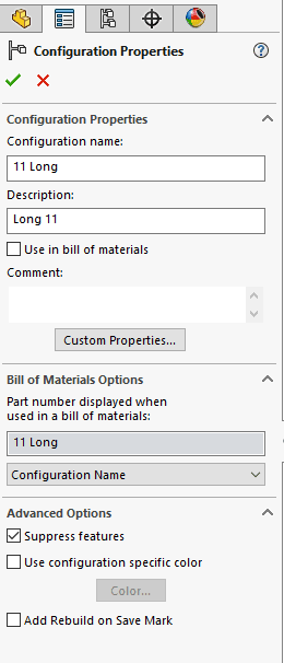
From here, we can specify the name and description of the new configuration, as well as set any necessary options. In this case, we are choosing to use the name of the configuration rather than the file name when this part is used in a Bill of Materials. We also chose to suppress new features in other configurations when they are added to this configuration. Any new configurations created using this method will retain the settings of the last used configuration.
As we change a dimension in the new configuration, we can specify whether we intend that change to remain contained within this configuration, specific configurations, or all configurations.
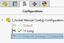
We can switch between the new configuration and the old one by double-clicking on them in the ConfigurationManager.
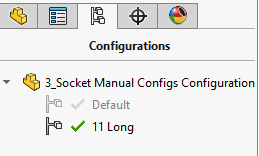
The highlighted, in color configuration is known as the “active” configuration. Configurations that are inactive but have a check mark have been rebuilt, but are simply not being viewed.
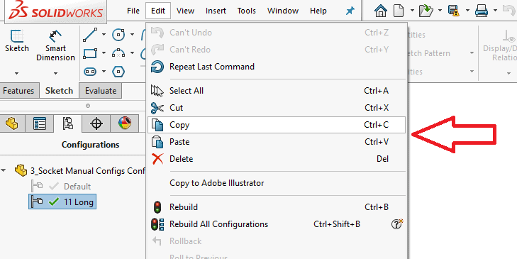
We will create another configuration by selecting the ’11 Long’ configuration and then clicking Edit, Copy and Edit, Paste.
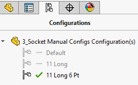
The newly pasted configuration appears in the ConfigurationManager, and can be renamed with a slow double-click
For this new configuration, we will suppress a feature by right clicking it in the Design Tree, and choosing “Suppress”
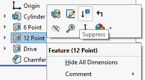
This feature is now suppressed for this configuration only.
Creating Configurations using the Configuration Table
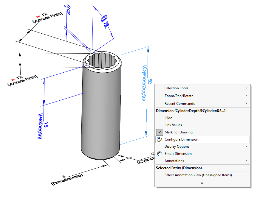
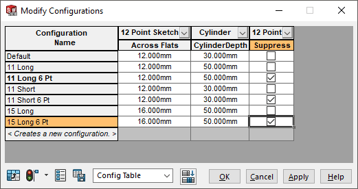
Another method we can use to create configurations is the SOLIDWORKS Configuration Table. We access the Configuration Table by right clicking on a dimension or feature and choosing “Configure Dimension” or “Configure Feature”.
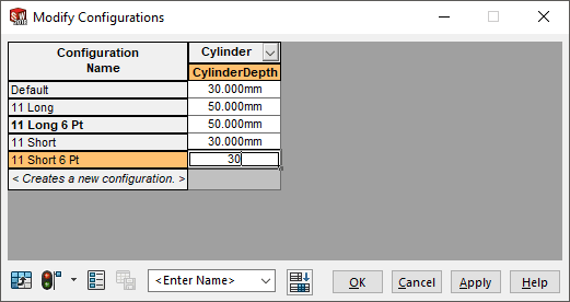
The resulting window that launches allows us to quickly create additional configurations and specify values for this dimension for the new configurations.
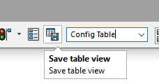
Once the table has been filled in, it can be saved by entering a name in the <Enter Name> field, and choosing “Save Table View”
The table is now saved and appears in the ConfigurationManager.
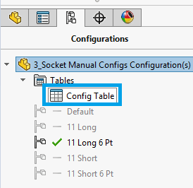
We can access the table by double-clicking on it, and we can add additional columns by double-clicking on the associated dimensions or features.
Creating Configurations using the Design Table
The last method we will look at for creating configurations is the Design Table. Design Tables are very similar to Configuration Tables, but use Microsoft Excel instead of the built-in SOLIDWORKS table editor. This gives us the full power of Excel, and allows us to use functions, formulas, and more as we configure parts and assemblies. (You must have Excel 2010 or later installed on your machine to use Design Tables in SOLIDWORKS)
To create a Design Table, click Insert, Tables, Design Tables… (notice the icon has a superimposed Excel logo). This will launch the Design Table PropertyManager
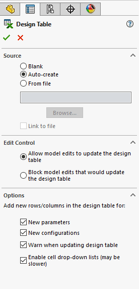
Here, we can specify if we would like SOLIDWORKS to create and format the table for us, or if we would like to use a blank or linked Excel file. (Formatting in Design Tables is very important, please see the Help article “Formatting a Design Table” for more information). We can also choose whether or not we want bi-directional associativity between the Design Table and the SOLIDWORKS file.
If we choose ‘Auto-Create’ and click OK, Excel will launch inside of SOIDWORKS.
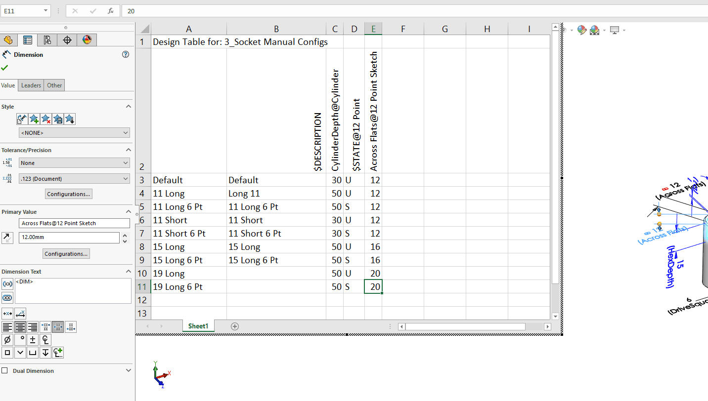
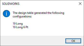
We can create new configurations by typing in the cells below the existing configurations. We can also edit dimension values or suppression states quickly by simply changing the values contained in the cells. Upon returing to SOLIDWORKS, we receive a message for any new configurations that have been created by the Design Table.
I hope you enjoyed this first installment in our Configurations series.
Configure responsibly,
Aarya Engineer
Application Engineer
Computer Aided Technology, Inc.