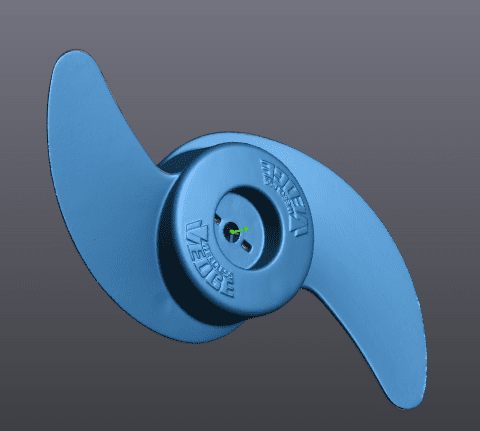
Deep Dive into Reverse Engineering a 3D Scanned Propeller
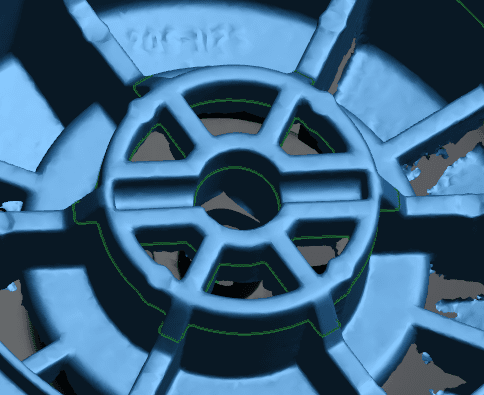
One of the main uses of 3D Scanners is reverse engineering, and this may seem like a daunting task. Today, we will be taking a look at this process and how we can accomplish this using VXmodel and SOLIDWORKS. For our example, we’ll be reverse engineering a propeller.
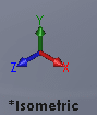
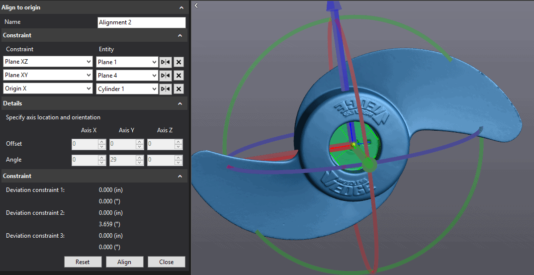
Once we have our 3D scanned propeller, we need to properly align it so that the origin and planes correspond with our CAD system to avoid extra steps later on in the process. There is a difference in what each software considers to be an isometric view. This is something that has caught me a few times.
VXmodel SOLIDWORKS
| SOLIDWORKS | VXmodel |
| Front Plane | XY Plane |
| Top Plane | XZ Plane |
| Right Plane | YZ Plane |
For this file in particular, I had to create four planes and one cylinder to create my alignment.
Plane 1 using Triangle Selection
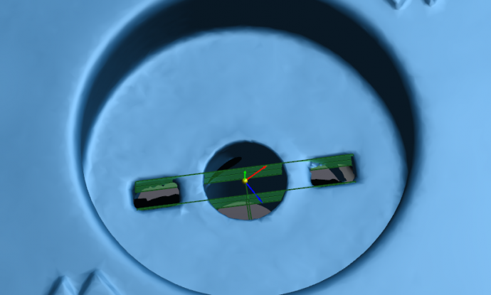
Plane 2 and 3 using Triangle Selection
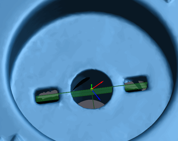
Plane 4 using Average Plane and Planes 2 and 3
Cylinder 1 using Triangle Selection with Orientation aligned with Plane 1
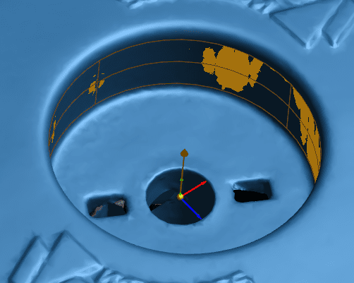
Once these planes are created, I can create an alignment using “Align to Origin.”
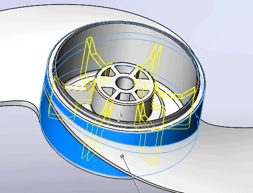
Now that our prop is aligned properly, we can begin reverse engineering it. We will start with the center portion. To guide this portion of the part I like to use a cross-section. In this case specifically, I’ll use a single radial cross-section offset 10 degrees off the “Origin-Plane XY.” Once the sketch is recreated, we need to revolve it around the central axis.
To make the blades, we will use Single Patch surfaces and a Silhouette cross-section.
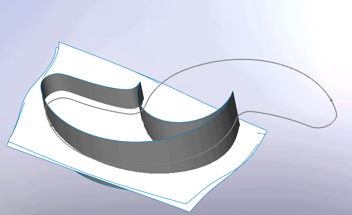
Once the blade is created we can pattern it and combine them with the hub body.
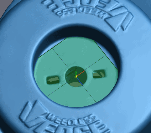
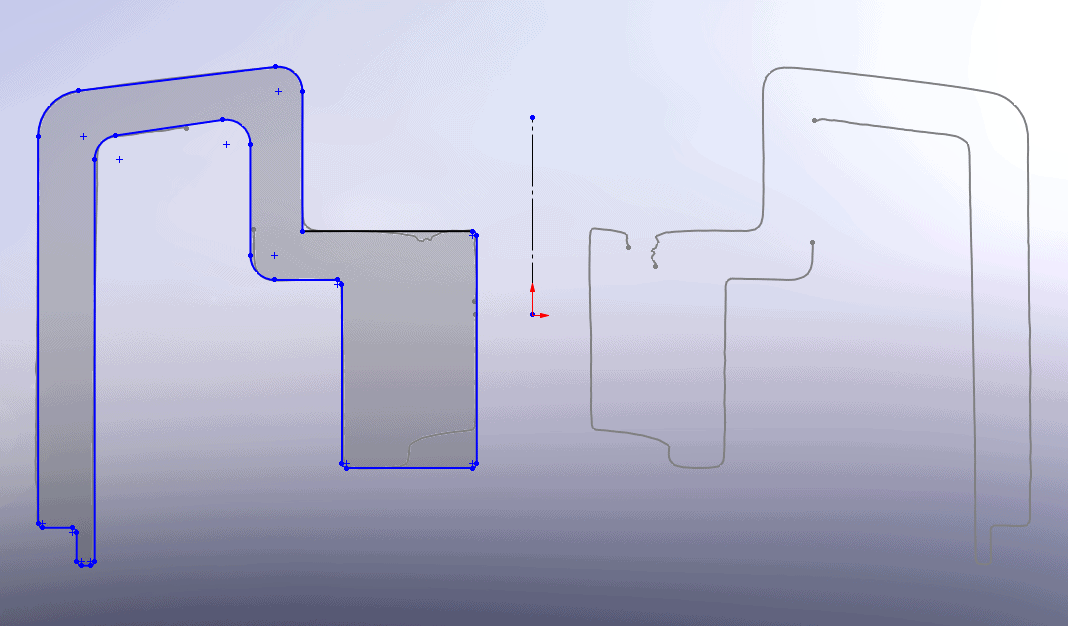
Now that the main body is complete, we can focus on the internal structure. We’ll start with a cross-section of the inside.
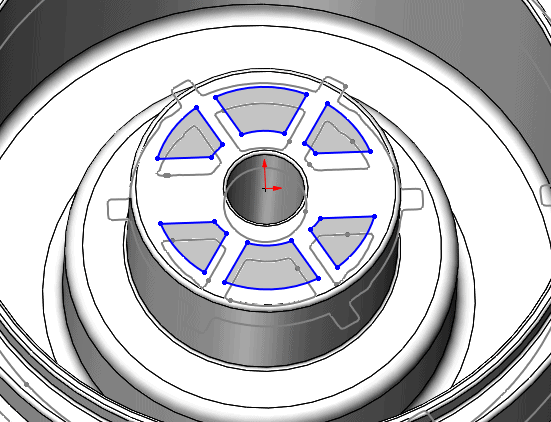
Now that the cuts have been completed, we need to make the larger ribs. Using a single radial cross-section to find the geometry and two parallel planes to find the thickness. A circular pattern will fill in the other instances.
We will then follow the same process to create the other smaller ribs. And to finish we just need to add some fillets to round some of the edges.
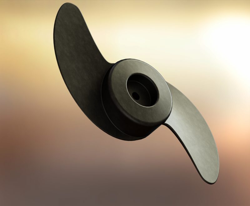
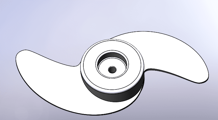
Completed Propeller
For any and all other questions regarding Creaform 3D scanners, contact Computer Aided Technology to get in contact with one of our local 3D scanning experts!
Chad Whitbeck
CATI Application Engineer
Computer Aided Technology