F123 Head Change and Calibration
You will need to replace a print head in your F123 series printer if any of the following issues exist:
There is a loss of extrusion caused by a clogged tip and you are unable to recover from the loss of extrusion.
You are unable to load material into the head and you cannot unclog the tip
You are having an issue with print quality or parts adhering to the tray and it has been determined that the issue is caused by the print head..
Any time the print head odometer reaches 1500 hours.
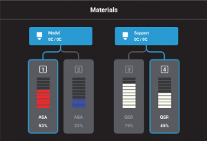
When the print head odometer reaches 1500 hours a warning will be displayed and the Head Status Icon will be highlighted in red on the Materials page.
You can continue using a head which has exceeded its odometer limit, but it is highly recommended that you change the head as the part quality will be unpredictable.
To replace a Standard Head follow the instructions below.
1. Unload the material from the head that will be replaced.
With the printer idle press Materials on the control panel. The Materials status screen will appear. Press the material bay you need to unload and then press Unload.
The border of the material bay being used is outlined in blue and the line between the Material Bay and the Head icon will also be blue as pictured below.
2. With the printer still powered on open the front and the top cover.
Note: Replacing a head while the printer is powered ON will ensure that an Automatic Tip Calibration is performed after the replacement process is compete.
You should always replace the F123 print heads with power on
3. Press on the release tab and unplug the ribbon cable from the head that will be replaced. The Model head is on the left and the Support head is on the right.
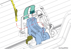
4. Disconnect the material tube from the print head being replaced.
5. Unlock the head release lever by pulling it toward the front of the printer.
6. Pull the print head out of its position and remove it from the printer.
7. Insert the new head into the same position and close the locking lever by pushing it to the rear of the printer. Make sure it latches the print head in place.
8. Connect the material tube.
9. Plug the ribbon cable into the new print head and make sure the cable latch is engaged.
10. Close the covers.
An automatic tip calibration will be performed prior to the start of the next build. You must always run an Automatic Tip Calibration then a Manual Calibration afterwards.
If a head was replaced while the printer was powered OFF, an Automatic Tip Calibration does not occur and you must manually initiate the calibration.
To do this follow the steps below.
1. Place a new substrate onto the platen and lock the substrate into its build position by lifting up on the handle.
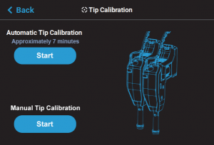
2. Open the Tip Calibration page by navigating to Tools > Calibration > Tip Calibration.
3. Press the Start button for the Automatic Tip Calibration option.
The printer will now run the Automatic calibration.
This process will take several minutes. When it completes press Finish.
After performing the Automatic Tip Calibration you must run a Manual Tip Calibration.
To Perform a Manual Tip Calibration:
1. Verify there is a new substrate installed in the printer. You cannot use one that has been printed on to run the calibrations.
2. Navigate to Tools > Calibration > Tip Calibration. Press the Start button for the Manual Tip Calibration option.
3. The Print Calibration Part page will be displayed and the printer will automatically select the correct calibration part for your configuration. Press the Start button.
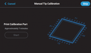
.The calibration part will begin to print.
Once the calibration part is complete “DONE” will be displayed.
Remove the substrate from the platen, you will analyze the part on the substrate to determine correction values.
Press the Next button in the upper right corner of the page; the Manual Tip Calibration page will be displayed.
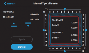
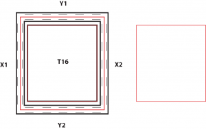
Using a magnifier (one was shipped in the Welcome Kit) determine where on each side (X1, X2, Y1, and Y2) the support tool path is most centered between the X-Y alignment indicators
as shown below.
The numbers on the calibration part represent thousandths of an inch (e.g., 4 = 0.004 in.).
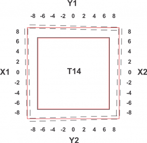
Slide all four of the scale icons on the screen to match where the support tool path is most centered between the alignment indicators.(two rows of Model material)
One value must be selected for each side.
The Delta X and Delta Y fields will change to reflect the adjustments made.
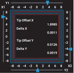
If the Delta X and the Delta Y values are both within the range of -0.002 to +0.002 in., the printer is calibrated and an adjustment is not required. The following figure shows an XY offset within
tolerance, requiring no adjustments.
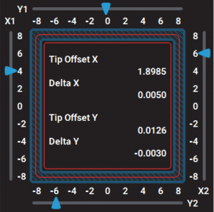
If either of the Delta X or Delta Y values are outside the range of -0.002 to +0.002 in., the printer requires an adjustment.
The following figure shows the Delta X value of 0.0050 in and the Delta Y value of -0.0030 in. are both outside of the acceptable range.
After sliding to your adjustment value(s) press the Apply button.
Your calibration adjustment(s) will be saved.
Press Finish.
You will need to print another Calibration part and adjust that also.
Do this until both the Delta X and Delta Y values are within tolerance, which is within -0.002 to +0.002 in.
Then proceed to the Z offset adjustment
Determine the Z Offset Adjustment.
A. Peel the support layer from the inner most square of the calibration part.
B. Measure the thickness of the support layer on each side of the square with a caliper or micrometer.
Measure in the center of each side; measuring near the corners will result in inaccurate values.
C. Take the average value of the four measurements, this is the number you will enter for the Z
offset adjustment.
T14 Tip slice height is .01 inch or .254 mm
D. Compare the number from C to the tip slice height.
E. If the value measured in step C is within ±0.0005 in. (0.01 mm) of the model tip’s slice height the printer is calibrated for the Z axis and an adjustment is not required.
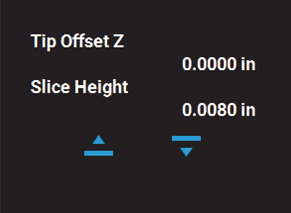
F. If the value measured in step C is not within ±0.0005 in. (0.01 mm) of the model tip’s slice height you will need to enter a Z offset adjustment using the Up and Down
buttons within the Manual Tip Calibration page. Each button press equates to one ten thousandths of an inch.
Use the Down button to enter the value obtained in step C if this value is less than the tip’s slice height.
For example, if you measured an average of 0.0080 in. (0.2032 mm) for a tip with a slice height of 0.010 in. (0.254 mm), press the Down button until 0.0080 (0.2032) is displayed within the slice height field.
Use the Up button to enter the value obtained in step C if this value is greater than the tip’s slice
height.
For example, if you measured an average of 0.0120 in. (0.3048 mm) for a tip with a slice height of 0.010 in. (0.254 mm), press the Up button until 0.0120 (0.3048) is displayed within the
Slice Height field.
If a Z offset adjustment is required you will need to rebuild the calibration part.
After entering your Z offset adjustment press the Apply button your calibration adjustment(s) will be saved.
You can use the Clear button to reset a value before you hit Apply. Once Apply is pressed the values are set in memory.
Be careful to not input incorrect values before hitting Apply.
Press Finish.
Build another Calibration part.
Continue to check and adjust for Z offset until the support layer matches the model tip slice height ±0.0005 in. (0.01 mm).
Once you’re finished adjusting for XY and Z, press the Apply button
A screen will be displayed momentarily and your calibration adjustment(s) will be saved.
Press the Finish button within the upper-right corner of the Manual Tip Calibration page to exit the page.
PLA Head Replacement
The process for replacing a PLA head varies slightly from the process for replacing a standard head. When building with PLA material a specialized PLA head is used.
The PLA head must be installed into the model head location.
A cooling module is used in conjunction with the PLA model head and must be installed into the support head location.
Automatic Tip Calibration is not performed during PLA head replacement.
Remember that the PLA head must be installed into the model head location (on the left) and the cooling module must be installed into the
support head location (on the right).
Both the PLA Head and the Cooling Module are removed and replaced the same way that a Standard head is replaced.
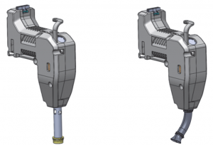
PLA Head Cooling Module