Gear Mate Galore!
Do you work with multiple gears and need rotation in an assembly? Tucked away in the Mechanical Mates dropdown of the Mate PropertyManager is the Gear Mate. The Gear Mate can be used to force two components (such as gears) to rotate relative to one another (with a desired ratio). In the scenario below, the two gears near the top are not mates relative to one another and can freely rotate around, often colliding.
You can use cylindrical/conical faces, axes, and linear edges to be the selections for how your two components rotate relative to one another. After selecting on your two components’ cylindrical/conical faces, axes, and/or linear edges, the Ratio input boxes populate automatically. This Ratio is based upon the diameter of the items selected. You can always manually edit/update the Ratio if the auto-populated ratio isn’t how you want your components to move.
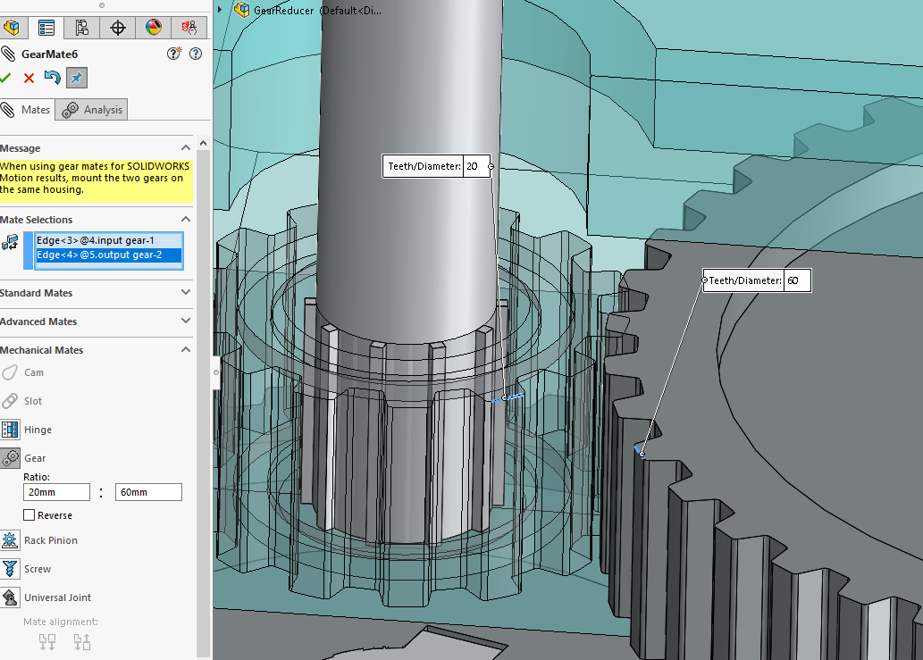
You might notice that the gears are colliding; that’s because the Gear Mate isn’t “smart” enough on its own to detect collision or interference. Before you create this Gear Mate, it’s good practice to have the gears (or components) positioned in such a way that there isn’t collision or interference occurring. (you can even use Move Component > Collision Detection to verify > place your components in such a way they are not in a colliding position to begin with)
Note that you do not have to use two gear components, but you can use the Gear Mate to mate any two components to rotate relative to one another.
Nathan Marsh
Application Support Engineer II