DESIGN FOR 3D PRINTING - Tips, Tricks & Techniques Part 2 of 3
Designing for Additive Manufacturing can be somewhat different than designing for traditional Subtractive processes (Mills, Lathes, etc.) We will break this down into 3 parts that impact your design, Design Considerations (part 1), Exporting Data (part 2) and Build Preparation (part 3).
In Part 1 we discussed Design Considerations. In this blog let’s take a detailed look at the next step – Exporting the Data. This can be equally important to define the form, fit and function intended for the designed part. We will focus on; Understanding the STL Format, Saving the STL file and Multiple Shells as an Assembly.
Understanding the STL Format:
The geometry of CAD (Computer Aided Design) models are generally defined by mathematical formulas. This works well for constructing parts, but AM (Additive Manufacturing) equipment cannot handle the algorithms of the wide variety of available CAD software. STL (Surface Tessellation Language) is the primary format for most AM equipment. It does not consist of parametric values, but rather triangles connected into a mesh covering the surface of the CAD model. All CAD packages have translators to export or save in the STL format.
Some 3D Printing software will allow you to bring the native CAD into the printer software without converting into an STL file. Most of these are merely using a built-in STL translator. In addition, this feature to import native CAD often does not allow the user to adjust any settings that would refine the triangle size on the part which defines the surface quality.
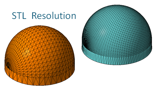
To create the STL file from CAD there are 3 minimum requirements. First, the CAD model must be a ‘water-tight’ volume, surfaces with an opening will not define a 3-dimensional STL file correctly because it lacks volume. Secondly, the resolution, CAD surfaces are approximated by polygons as shown below. A higher STL resolution = more polygons = higher accuracy = larger file size. And lastly, you must define the units; inches, millimeters, centimeters, etc. For example, a triangle defined as .004 will work in inches but a triangle defined as .004 in millimeters would be too small and create an enormous file size.
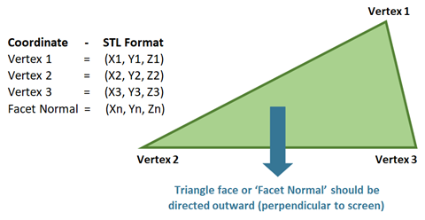
The triangle vertices are defined in a 3D coordinate space. In addition, each triangle surface that must be facing outward, this surface direction called the ‘facet normal’. An inverted triangle (triangle not facing normal) may be ignored in the 3D printing process.

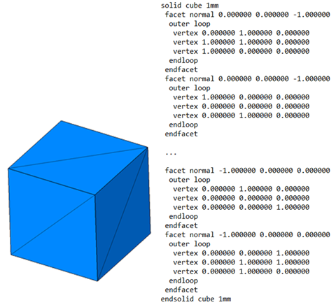
The STL file can be saved as ACSII (American Standard Code for Information Interchange) or Binary (Base 2 Numeral System; representing information using the numbers 0 and 1). Binary is the prefered format as the file size is about 6 times smaller than ASCII. Even when saved as binary the file can be opened with a text reader, such as Notepad, and displayed in the ASCII format. Below is an ASCII example of a simple cube, 1 x 1 x 1 mm created by 12 triangles, you can see the construction of the triangles as defined by Facet Normals and the triangle vertices designated in 3D Coordinate Space.
The size of a good STL file will always end in ‘34’ or ‘84’ bytes. This is because the header = 80 bytes, the number of triangles = 4 bytes and each triangle = 50 bytes. The total file size will be the Triangle Qty. X 50 + 84. If the STL file does not end in 34 or 84 bytes it is a bad or corrupt file that is not defined properly.
Saving the STL File:
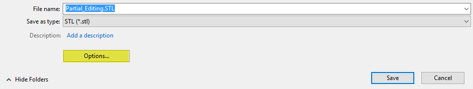
Most CAD software programs will save an STL file with a simple ‘Save As’ or ‘Export’ command. In Solidworks, it is a simple sequence of File > Save As and a window appears asking for the file name. However, there is an Option button here that is often overlooked. This is where you can refine the detail level of your STL file.
Think of these options as resolution or even accuracy settings since they will dictate how the model that is 3D printed will look. Here you can set the STL in Binary, as discussed in the prior section above, and select the units. Even if the CAD design is drawn in mm you can select the STL output to be in inches.
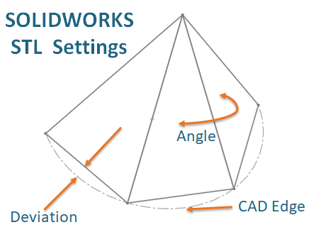
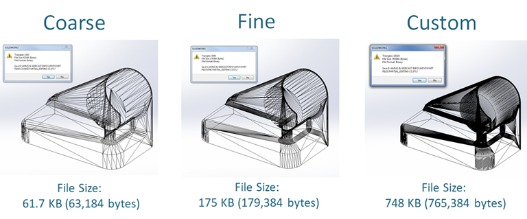
In Solidworks there are basically 3 Resolution choices; Coarse, Fine and Custom. Coarse will produce a highly faceted part with large triangles. A Fine setting will produce smaller triangles, but Custom will allow you to select the controls to achieve the best-looking 3D printed part. The Custom option will allow you to use the Deviation and Angle settings.
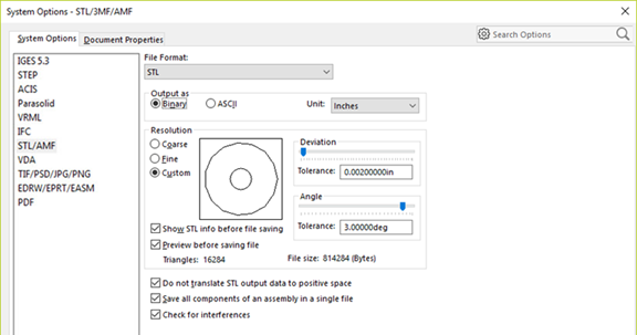
Deviation refers to the maximum distance that the triangle of the STL file is permitted to be away from the original CAD geometry. The angle setting refers to the angular divergence allowed between adjacent triangles. Lower numbers on these settings will result in smaller triangles with a closer representation of the CAD design.
Be aware, that you can get too low and significantly increase your processing time to generate a file as well as increase the file size. From personal experience, I have found a deviation of .002 – .004 inches and an angle setting of 2- 5 degrees to be acceptable for most 3D printed parts.
Multiple Shells as an Assembly:
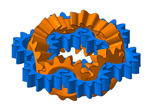
A ‘shell’ in 3D printing is defined as a closed model. In Solidworks a closed model is called a solid body. Every 3D printed object must have at least one shell. Multiple shells can be used to create an assembly or to create functioning parts. However, it is important not to confuse assemblies with overlapping shells. Many STL errors are created in CAD with overlapping shells and intersecting triangles, below is a cross section of a simple part showing errors created from overlapping shells.
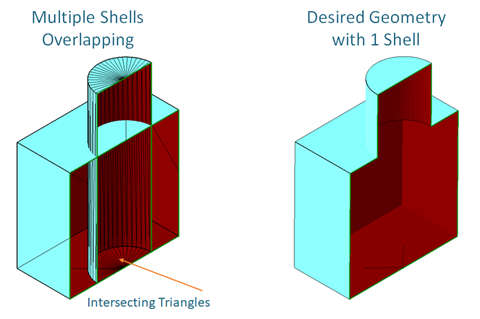
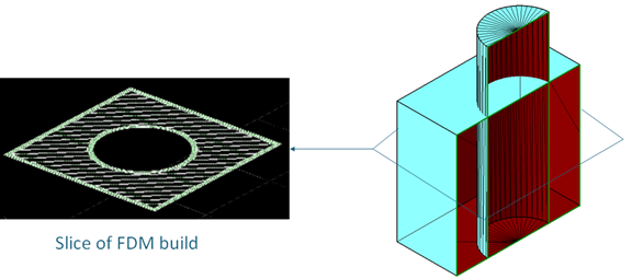
The result of the overlapping shells will confuse 3D printers when trying to distinguish the surface for the perimeter and the internal fill tool path. For example, the picture below shows how FDM will draw a single layer of overlapping shells.
For an assembly the shells or solid bodies should be drawn in CAD separately (without overlap) with the appropriate clearance. Then 2 shells can be recognized by the 3D printer and drawn without error. When saving the STL file with the Options button, previously described in the section above, checking or unchecking the option ‘Save all components of an assemble in a single file’ allows you save the assembly as a single STL file or individual STL files for each body. Both options can be useful for 3D printing.
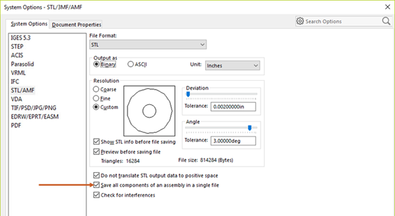
Checking the box will create only 1 STL file with multiple shells and with the appropriate clearance a single functioning part can be 3D printed. There is not a problem with multiple shells, if they do not overlap.
Unchecking this option will save each solid body in the assembly as a separate STL file, each with 1 shell. To keep each STL file in relation to their position within the assembly, check the box for ‘Do not Translate STL output…’ . PolyJet technology can load the individual STL files as an assembly and allow different colors or material properties to be assigned to each individual shell.
Summary:
As discussed, the basics of creating a 3D printable file consist of; Understanding the STL format, Saving the STL file and using multiple shells or solid bodies in an assembly. In the next blog, part 3, we will examine the final installment of Build Preparation, focusing on part orientation and build speed
Mark Abshire
Sr. Application Engineer, Additive Manufacturing
Computer Aided Technology, Inc