How to Make Threads in SOLIDWORKS: Basic and Custom
 Welcome back to part three of my “how-to” blog series. In part one of this series I showed how to make a screw in SOLIDWORKS, and in part two I showed how to make a helix in SOLIDWORKS. In today’s blog, we’re going to take a look at how to make threads in SOLIDWORKS. The good news is that ever since the release of SOLIDWORKS 2016, the process couldn’t be easier. There are basic threads and custom threads. I’ll show you how to make both. Let’s get started.
How to make a thread in SOLIDWORKS – Basic
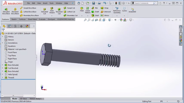
To make a thread in SOLIDWORKS we can simply to go Insert > Features > Thread. We then choose an edge of our model and go through and populate our thread specifications. Once we’re done doing that, we can hit the green checkmark and there are our threads. It really doesn’t get any easier than that.
But a lot of users want to know how to create their own threads in SOLIDWORKS by sketching their own profile and doing a sweep cut.
How to make a thread in SOLIDWORKS – Custom
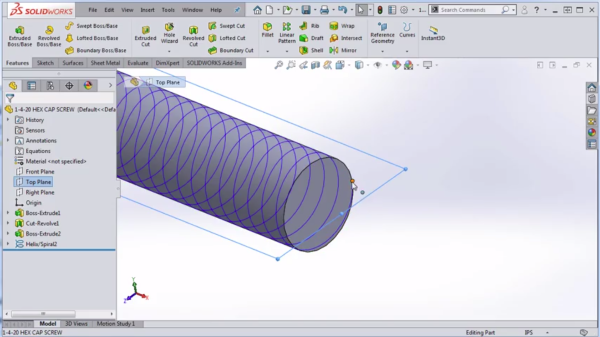
To do this we’re going to start off with the helix we created in my previous blog as we were modeling this hex cap screw. Go to the top plan and begin a sketch. Now, the reason we’re using the top plane is that when we created the helix, the helix ended at zero degrees so that’s exactly where our top plane is.
So we’re going to begin a new sketch on the top plane and now we’re ready to sketch the actual thread profile. This is where the real magic happens because there’s a lot of different techniques on how to do this, where should the plane be located, and ideally you’re going to stick the specifications in the Machinery’s Handbook – but if you don’t have those specifications or if you’re creating a custom thread, then you might have a little bit more play as for how you create your thread.
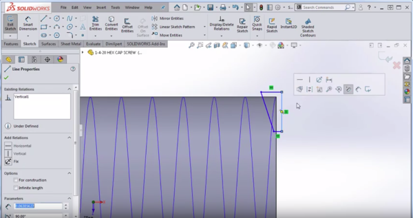
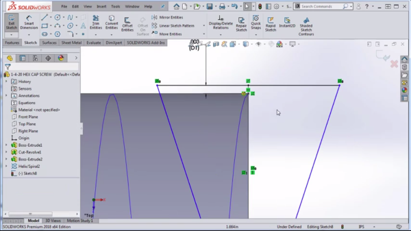
Personally, I like to create half of the thread at first and then I take the vertical line (as shown below) and make it for construction. Next, I’ll take a window selection of the entire sketch and select the Mirror Entities command which gives me the same thread profile on both sides of the center line.
Next, I will take a point and put it kind of anywhere on the center line and then put a dimension from that point to the very top line. The reason I have that dimension there is because I want there to be a little bit of overlap between where the thread is cutting and the very outer most part of the shaft by just a few thou (maybe 0.003 inches).
Now I’m going to click on that point that I had sketched and I’m going to hold CTRL and select the helix and I’m going to assign what’s called a pierce relation. That’s going to hook that sketch to the helix exactly at that point.
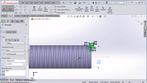
Now I’m ready to put in my final dimensions and say I want the distance from peak to peak to be .042 (the pitch is .050 so that should give me more or less than the ballpark). I[‘m going to make the flat at the bottom 5 thou just to get myself close. Reminder: I know these aren’t exactly the right numbers from the Machinery’s Handbook but I’m just trying to give you something close to work off of.
Finally, I’m going to put in a dimension, maybe I’ll take the pitch dimension, grabbing the midpoint of that line, drop in a center line, drop a center line off of the origin and I want the pitch diameter to go from this point to the center line that I created and then across.
If I look at my spec sheet, it is .2127. Now that should give me something that looks pretty good for this cut thread and again, it’ll be up to you to make sure your numbers are exactly perfect. I’m just trying to get in there and show you how to make the sketch.
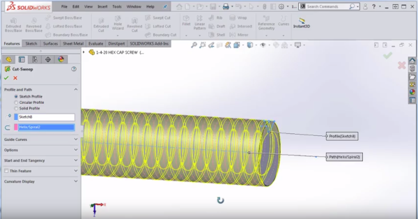
So now I’m going to exit that sketch and I’m going to go to the command Features > Swept Cut and I’m going to choose to sweep that sketch that I created along the helix that I created in the previous blog. I’m seeing a preview which means I should be in the right direction and then hit the green check mark and there we go, we were able to do a cut sweep of those threads.
To create the lead in for this part up at the top, I like to create a simple cut revolve. You don’t have to do this with a chamfer, in fact, you might struggle to do it with a chamfer because there’s not really a clean edge there to chamfer off but you can do it quickly and easily by creating a simple triangle. To see how this done and a video demonstration of this entire process, be sure to watch the video below.
I hope you found this guide to be helpful on how to create threads in SOLIDWORKS. In my next blog, we’re going to talk about how to assign material to this hex cap screw. Stay tuned.
Related Articles
How to Make a Helix in SOLIDWORKS
How to Make a Screw in SOLIDWORKS
Learn SOLIDWORKS With a Customized SOLIDWORKS Course Guide
About the Author
 Toby Schnaars began using the SOLIDWORKS Software on the ’98 plus release, in October of 1998. Toby is currently a Technical Sales Manager at Dassault Systemes SOLIDWORKS. He has fielded over 10,000 tech support cases and been the head instructor for over 200 SOLIDWORKS training classes. Toby is a regular presenter at users groups, technical summits, and SOLIDWORKS world. In 2003, in Orlando, FL, Toby won first place in SOLIDWORKS MODEL MANIA a modeling contest based on speed and accuracy.