How to Make a Screw in SOLIDWORKS
 For today’s tech tip we’re going to talk about how to make a screw in SOLIDWORKS. This is the first in a series that will cover the process – we’re going to start out by making the head of the screw, we’re then going to create a helix, followed by sweeping some threads along that helix, then we’re going to assign the material to the screw, and finally we’ll create both a left hand a right-hand version of the screw. Let’s get started.
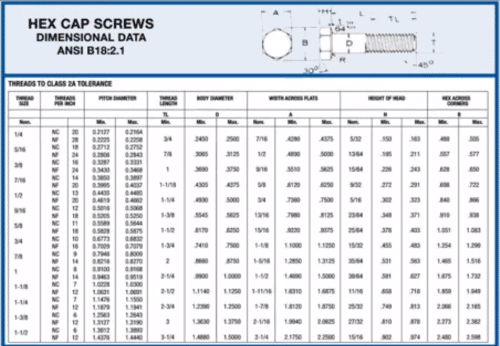
The first step we need to take is to decide what type of screw we’re going to create. In this case, I’ve downloaded the specifications for a hex cap screw so I’ll just create the first screw on this chart – a ¼ 20 hex cap screw.
Now that I’ve decided what type of screw to create I’ll start a new part. In this case, I’ll start it as a part in inches since the specifications are in inches. Next, go to the right plane and begin a sketch and then begin the polygon tool. The polygon tool in sketch mode allows you to create a polygon with any number of sides. I’m going to choose six sides and drop the polygon in place.
A quick note on the polygon tool is that you can still rotate the polygon tool after you drop it so you want to make sure that you select one of those points and then assign a vertical relationship to the origin, that way you can no longer rotate the polygon.
Pay attention to the Instant2D Command
To add the first dimension, I can reference back to the specification and see that this is going to be the “A” dimension, the flat to flat on the hex and that the dimensional value is .4280. Once you have your fully defined sketch we can extrude it – but before I do that I can go to the pull-down menu and hit “view dimension names” and go to the command Instant2D to make sure that it’s NOT enabled. Next, click on the dimension, click the upper section of the box, and change the dimensional value to “A”. That way you can see the dimensional value as “A”.
Next, go to Features > Extruded Boss/Base and extrude that out to the set distance. In this case, the distance will be our “H” dimension which is .150 (make sure that it’s going in the correct direction). Just like with the “A” dimension we can make sure that Instant2D is not enabled, we can then double click on the head, double-click on the .150 and change the dimension to “H”. This makes it much easier if you decided to take the model, do a save as, and give it a new name, define a new size, or maybe go in and work with configurations to define some new sizes – it’s going to be much easier if these dimension names are aligned to our specifications chart. Once the model is saved, you can start rounding off the head.
How to round off a screw head
Go to the front of the plane and begin a sketch – start by creating a center line right down the center of the head of the screw. Next, create a simple triangle with a dimension as the specification defines (in my case 30 degrees) and define the diameter as the same as the “A” dimension.
Quick tip: A little quick trick you can do here in SOLIDWORKS, is you can say you want the dimension to equal, double click on the head to bring up its dimensions, and then you can click on the “A” dimension. What this does is that it sets us up so that the diameter of the cut round that we’re going to do, (Features > Revolved Cut) the diameter of the cut round on the inside is always going to touch off exactly at tangent of the flat to flat distance because the diameter is the same as the flat to flat distance.
So again, when we move forward, if we decide to make a different size screw, we can just double click on the dimension, change it to a larger size, and you will see that both of the dimensions update. Pretty awesome trick.
That wraps up this tip for how to make a screw in SOLIDWORKS. In the next blog, I’ll cover how to create the shaft and then create the helix. Stay tuned. For a video demonstration of how to make a screw in SOLIDWORKS, watch the video below.

Related Articles
How to Create Manual Configurations and Design Tables in SOLIDWORKS
Learn SOLIDWORKS with a Customized SOLIDWORKS Course Guide
Edit an STL file in SOLIDWORKS – It’s Easier Than You Think
About the Author
 Toby Schnaars began using the SOLIDWORKS Software on the ’98 plus release, in October of 1998. Toby is currently a Technical Sales Manager at Dassault Systemes SOLIDWORKS. He has fielded over 10,000 tech support cases and been the head instructor for over 200 SOLIDWORKS training classes. Toby is a regular presenter at users groups, technical summits, and SOLIDWORKS world. In 2003, in Orlando, FL, Toby won first place in SOLIDWORKS MODEL MANIA a modeling contest based on speed and accuracy.