How to create Manual Configurations and Design Tables in SOLIDWORKS
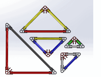 Have you ever needed to create a series of parts that were similar but slightly different in a few features, dimensions, colors, etc? In SOLIDWORKS, you can easily create a part then configure it to the exact specifications necessary for the other parts without the tedious recreation process. In this blog, we will use K’NEX pieces to demonstrate this process.
This is the first in a series of two blogs based on configurations modeled by K’NEX. Today we will discuss how to manually configure K’NEX connectors and then how to use a design table in SOLIDWORKS to configure K’NEX rods. In part two, we will discuss how to configure a K’NEX assembly and how to use tools like DriveWorks to create configurations. Let’s get started.
SOLIDWORKS Manual Configurations
Here is a standard K’NEX piece with eight openings.
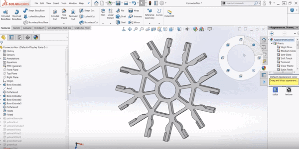
This is the same geometry as other K’NEX pieces, but with slightly more than necessary. We have added cuts and extrudes to make different geometries out of the same original geometry to create different parts.
To unsuppress all of the yellow cuts extrudes and fillets which will create a completely new piece. To configure these to make many different features in the same file by using the suppresses.
Under configure feature, we will see a list of all the configurations by simply clicking them and saying “configure features”, add all of the configurations that you’d like. By doing this we can then see what features we would like to suppress and which features we’d like to show and we can create many different parts. To view this process, view the video below.
Creating a Design Table in SOLIDWORKS
Now let’s discuss a design table where we’ll create it with rods and K’NEX. Here we have the original sketch of a rod in one profile.
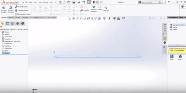
In my example, my measurements are all constrained and mirrored over to create the rod. Make sure to turn on show dimension names, I’m going to change mine to length, so it can easily be referenced later.
Once we exit the sketch we can revolve the feature around the center base axis. Now we have to add the different divets in the parts that can interconnect with the K’NEX in another way.
Once that is complete we will cut extrude the feature to create the divet in the piece. Once the first divet in the K’NEX piece is complete I’ll add fillets and put it in four different instances around the entire body.
Since we don’t want to go through all those steps again and again for each new piece and although the manual configuration was useful, it took a bit of time so instead, we’re going to make a design table. The video below shows how.
I hope you enjoyed this video tutorial. For more SOLIDWORKS tutorials check out the related articles below.
 ,/a>
,/a>Related Articles
Beginners Surfacing Breakout Session at SOLIDWORKS World 2018
Introduction to SOLIDWORKS Mold Tools
How to use SOLIDWORKS Treehouse and Templates to Create Assemblies Faster
About the Author
 Madison Bryce is a sophomore at the University of Michigan. She is studying mechanical engineering with a minor in computer science. Madison has four years of CAD experience and joined the Fisher Unitech team to share and grow this knowledge. Madison is a Certified SOLIDWORKS Associate (CSWA), Certified SOLIDWORKS Professional (CSWP), and a Certified DriveWorksXpress Associate. Madison’s dream is to one day become a roller coaster engineer. She is currently in a theme park engineering group at the University of Michigan.