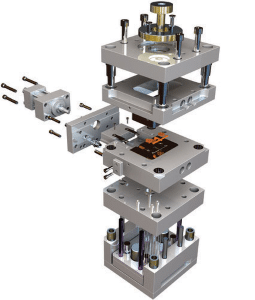
Introduction to SOLIDWORKS Mold Tools
 Another exciting SOLIDWORKS World event has come to a close, where over 5,000 SOLIDWORKS users attended and brought home new knowledge to incorporate into their everyday workflow. If you weren’t able to attend, or you’re new or unfamiliar with SOLIDWORKS Mold Tools, this blog is for you.
SOLIDWORKS Mold Tools are available in SOLIDWORKS Standard, SOLIDWORKS Professional, and SOLIDWORKS Premium and is offered for online and classroom training from our training team. The following blog was presented by our own Fisher Unitech SOLIDWORKS Expert Chaz Stipkovic, adapted from his breakout session at SOLIDWORKS World 2018. Let’s take a look.
In this blog, we’re going to cover the following areas:
-
-
-
-
- – The six core SOLIDWORKS Mold Tool features
- – Compare the differences between using SOLIDWORKS Mold Tools and manually generating core and cavity blocks.
- – Creating tooling bodies and reviewing the architecture of the Surface Bodies folder.
- – Review possible failure points for the Tooling Split command
The SOLIDWORKS Mold Tools Interface
To enable the SOLIDWORKS Mold Tools interface, right click on the Features tab (or any Command Manager tab) in the command manager and select “Mold Tools”. This will activate the Mold Tools tab.
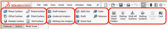
The SOLIDWORKS Mold Tools interface can be broken into four main areas (from left to right):
-
-
- – Surface Preparation tools, which lists common surface tools
- – Three Analysis tools
- – Four Model preparation tools
- – Mold Tools
-
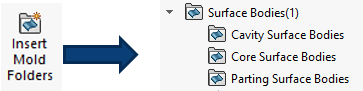
When you press the Insert Mold Folders button, three folders are automatically created under the Surface Bodies folder: Cavity Surface Bodies, Core Surface Bodies, and Parting Surface Bodies. The next steps will fill these folders, define where the Core or Cavity split will be.
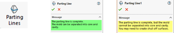
Next hit the Parting Lines button to define your Parting Lines. The image below shows the two possible dialogs. What do these colors mean? Green means a Cavity or Core surface was created and yellow means that there are “holes” through the part that need to essentially be plugged with Shut-off Surfaces. Once the Parting Line is complete (and Shut-off Surfaces, if necessary) the Cavity and Core Surface Bodies will appear in their respective folders.
Now we’re at the Parting Surfaces button. This creates the Surface which will split the tooling that we’ll create next. This can be done using the automatic tools or manually if the parting line is too complex.
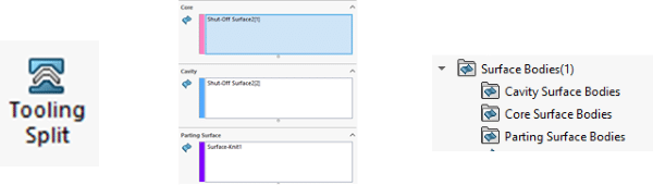
Finally, the Tooling Split command uses the surface bodies created in the folders above to split the tool body, creating the solid Cavity and Core. If necessary, the Core command can be used to create features such as side cores, lifters, and core pins if action is required in the mold.
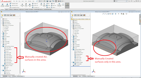
SOLIDWORKS Mold Tools compared to manually generated Core and Cavity blocks
The manual method requires that all the part cutting surfaces be defined manually for both the Core and the Cavity (shown below). In this example, that process took nine minutes. Using the SOLIDWORKS Mold Tools, those part cutting surfaces were generated automatically. This is where the real time savings can be had, in this case taking six minutes (saving three minutes!). This was a simple part with only about 30 surfaces needing to be picked. What if there had been 200 surfaces?
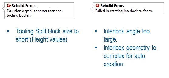
Trouble Shooting potential “Tooling Split” errors
The following are some of the possible Tooling Split errors and items to check to resolve them.
Tooling Split surface tests – can “Tooling Split” succeed?
If the tooling split fails and nothing stands out as incorrect from the above errors, try manually knitting the appropriate surfaces together (using surfacing tools) to check whether the tooling split can succeed.
-
-
- – Can the surfaces in the Cavity Surface Bodies folder be manually be knit with the Parting Surface Bodies?
- – Can the surfaces in the Core Surface Bodies folder be manually knit with the Parting Surface Bodies?
-
If not, the Tooling Split command will fail as well. Use Surfacing Tools to correct the surfaces so that they can knit.
Do we need to use each of these tools? No. They can be used in combination with manual methods as well. Are Mold Tools always the best solutions? No, sometimes it’s faster or plain easier to create the Cavity and Core through alternate methods. However, when they are a good fit for your part, the SOLIDWORKS Mold Tools feature can
-
-
-
- – Save time in Cavity and Core creation
- – Guide you through the steps you need to make a successful Core/Cavity
- – Make splitting surfaces easier to create
- – Automatically organize surfaces in the appropriate surface folders
- – Make side Core/Lifter/Ejector pin creation easier
Related Articles
2 SOLIDWORKS Tips for Working with Large Assemblies
About the Author
 Chaz Stipkovic is an Application Engineer Instructor based out of Pittsburgh, Pennsylvania. Chaz earned a Bachelor of Science degree from Penn State University in Mechanical Engineering Technology and Plastics Engineering Technology. He has been part of the Fisher Unitech family for 10 years, spending 9 of those years as a Technical Support Engineer specializing in Mold Tools. Chaz is a Certified SOLIDWORKS Expert with certifications in Mechanical Design, Plastics, Training, and Support.
 -
-
-
-
-