SOLIDWORKS Threads
From time to time designs will require threads. Threads can be fascinating to look out, but all threads are not created, nor behave, equally.
Take the below:
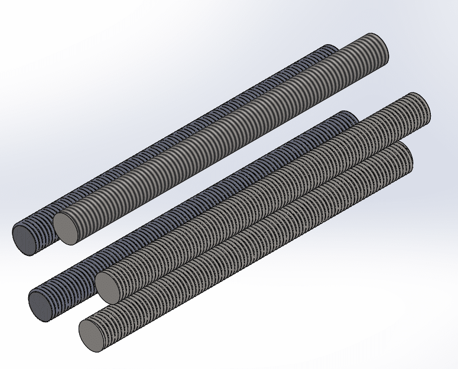
These are 5- 1”-8 threaded rods that are 12” long. These were all created in different methods. Starting with the top and going clockwise, they are
1 – Simple extrusion with cosmetic threads applied
2 – Extruded rod with a revolved thread cut and patterned
3 – Rod with the thread command cutting threads
4 – Rod with a cut-sweep utilizing the ‘Profile Twist’ – ‘Specify Twist Value’ option
5 – Rod with a cut-sweep following a helical path.
When it comes to threads, you really need to determine the value added by modeling them. You can tell that all 5 parts above are threaded. Here’s where the real deal breakers come in:
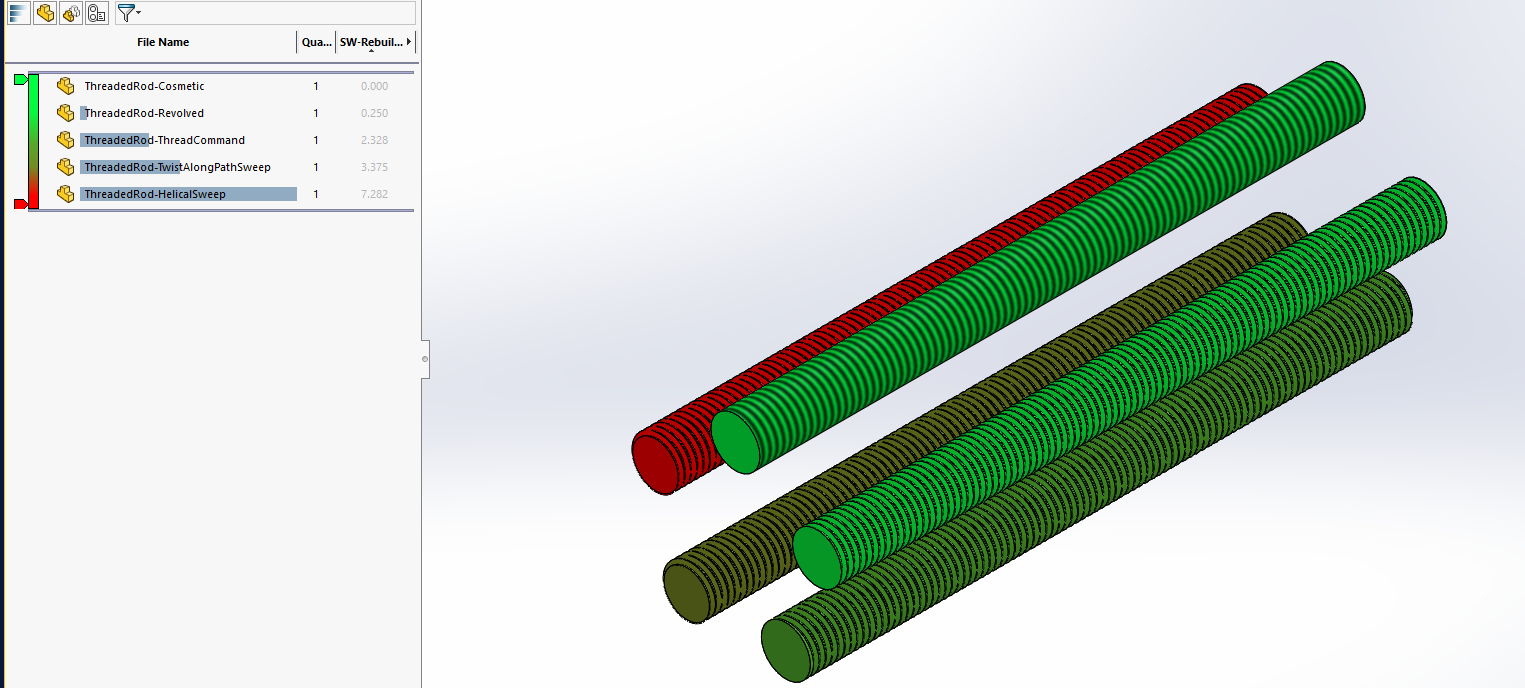
This is a view of the parts rebuild times via Assembly Visualization (Tools -> Evaluate -> Assembly Visualization). Here, we can see that all of our threaded rods take various amounts of time to rebuild. The Helical sweep takes 7 ¼ seconds, while the thread command will bring this down to 2 1/3 seconds. There are situations where modeled threads are required (especially if 3D printing). If all you’re going for is a look, then revolved threads can be useful as the rebuild time for that threaded rod was only 1/4s. The cosmetic threads (shaded cosmetic threads will only show up in shaded views), have 0 noticeable rebuild time at all.
With this in mind, some general tips for working with threads would be to have multiple configurations of your parts. While you may need threads shown on part level drawings, if you can switch to cosmetic threads for assemblies, you can significantly increase performance. Another way to check performance concerns is by going to Tools -> Evaluate -> Performance Evaluation. In here we can see a section titled ‘Display Performance’ with a sub-heading of ‘Graphics Triangles’.
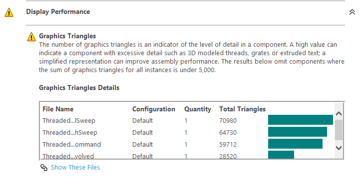
This is showing us that all 4 parts that aren’t using shaded cosmetic threads have more than 5,000 graphics triangles that get processed. The true threads range from around 60k to around 71k triangles. The revolved threads, which give a similar threaded appearance only have about 28.5k triangles. The fewer triangles, the better, more responsive behavior you’ll see in your models.
Another point to note is that threads are an extreme example of ‘cosmetic geometry’. While this is geometry that can be critical on a part level, I consider this ‘cosmetic geometry’ as at upper levels, its only purpose is cosmetic. Non-essential fillets and chamfers are another example of this. While you may want your parts to have rounded corners, those fillets will add graphics triangles/faces/edges to calculate. When viewing a 1,000 part assembly, these features aren’t required and will slow down your modeling. Having simplified configurations of your parts for use in higher assemblies will increase your performance by not having to calculate/generate all of the extra faces/edges on screen. This can be true for things such as hole patterns for vents, or expanded metal mesh. You can make something that looks good for part drawings, but at the assembly level, it complicates and slows things down where a simple planar extrusion could work just as well.
Fred Zobel
Senior Support Engineer
Computer Aided Technology, Inc