Control Your Flow Mesh
Mesh control is important no matter what Simulation product you use. The power of mesh control allows refinement of the mesh in areas of importance to the Engineer. This blog will focus on the mesh and mesh control used in SOLIDWORKS Flow Simulation.
SOLIDWORKS Flow Simulation software is a Computational Fluid Dynamics (CFD) analysis tool. SOLIDWORKS Flow Simulation offers users internal and external analysis of fluid systems. Steady State, Transient, and conjugate heat transfer solutions are standard with SOLIDWORKS Flow Simulation. Flow Simulation works seamlessly inside of SOLIDWORKS and offers an easy to use interface.
SOLIDWORKS Flow Simulation’s mesh is orthogonal and generates a Basic Mesh throughout the computational domain. The Initial Mesh is created by refining the Basic Mesh based on user settings.
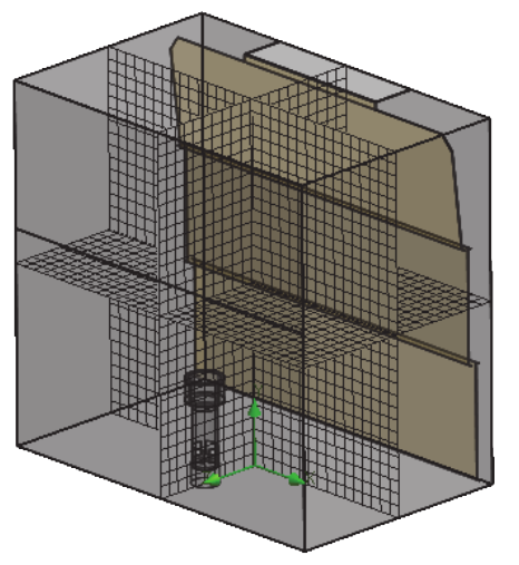
SOLIDWORKS Flow Simulations Initial Mesh can be refined and adjusted several different ways. The most direct way to refine the mesh in an area of interest is to use the Local Mesh option.
The Local mesh option is specific to refining the mesh in a local region. For example, an inlet/outlet area, a small geometry feature, or a general area that a very accurate goal value is required. The local region can be applied to a component, face, edge, or vertex.
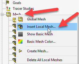
To use the Local Mesh option RMB on the mesh folder in the Flow Simulation tree.
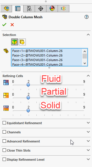
The Local Mesh gives a host of options. With the most important ones being located at the top of the property manager. Three types of cells can be adjusted: Fluid, Partial, and Solid (heat conduction in solids activated). It is important to refine all the available cell types, not just one. This gives a uniform growth and refinement to the cells. With a large size discontinuity between cell types, issues can arise including High Mach number Warnings (dependent on geometry), solution divergence, and incorrect reported result values.
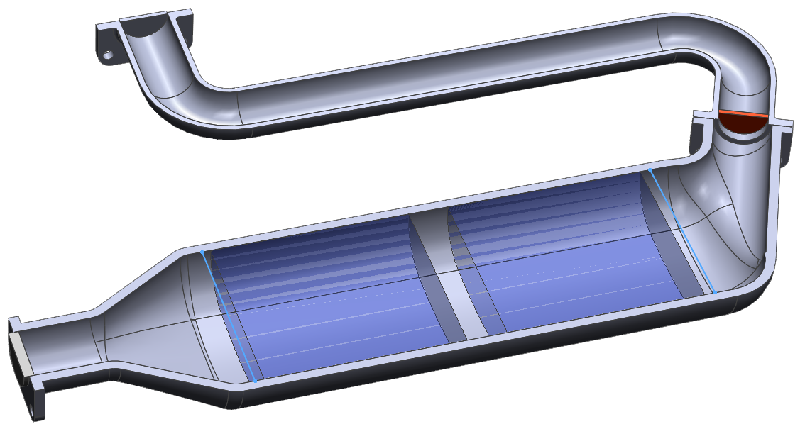
A good example of this Is a catalytic converter model. Flow through the porous catalyst elements is measured and reported by an XY plot. The sketch lines on either side of the catalyst bodies are the measurement reference for the XY Plot (represented in blue).
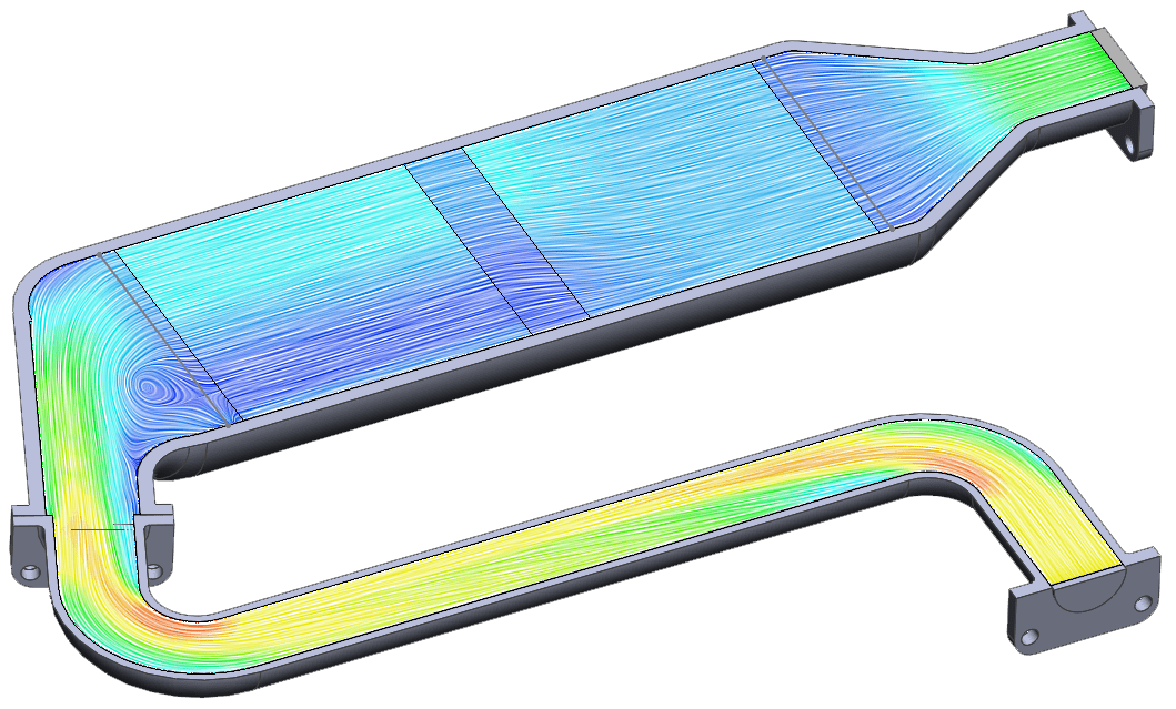
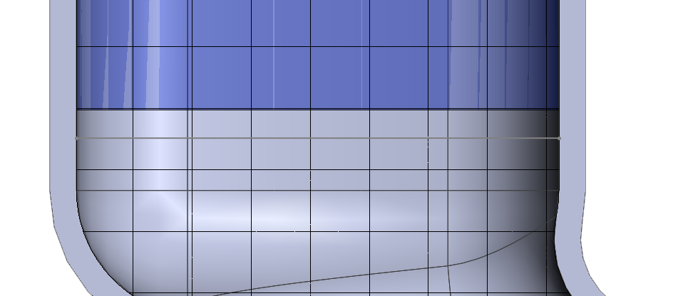
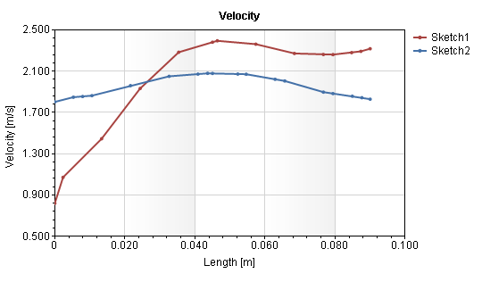
Using just the Global Initial Mesh the cells are large at the walls of the catalytic converter. This is asking the partial cell near the wall to cover too much fluid and boundary area to accurately depict what is happening close to the wall. Based on fluid mechanics we would expect a zero velocity at the wall. Based on the XY Plot we are presented with a mixed result of velocity.
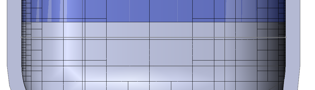
By setting a Local Mesh along the walls of the catalyst, a good refinement of the boundary layer is achieved. Small Partial cells and adjacent Fluid cells are meshed and grow larger towards the center of the fluid channel.
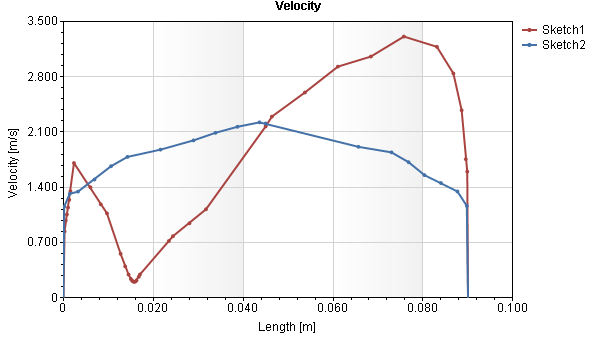
Adding this Local mesh refinement calculates the velocity at the walls to be zero as expected. Applying appropriate mesh settings to the important areas of the fluid model provides reliable, accurate results. To read up on Flow Simulation Mesh Practices select the link here. To learn more regarding best mesh practices attend a Simulation Training Class at Computer Aided Technology today!

Robert Warren
Simulation Specialist, Elite Application Engineer
Dad, Husband, Mechanical Engineer, Jeep and Sasquatch Aficionado
Computer Aided Technology, LLC