In Depth Reverse Engineering Workflow Part 1 : Scan to 3D Print
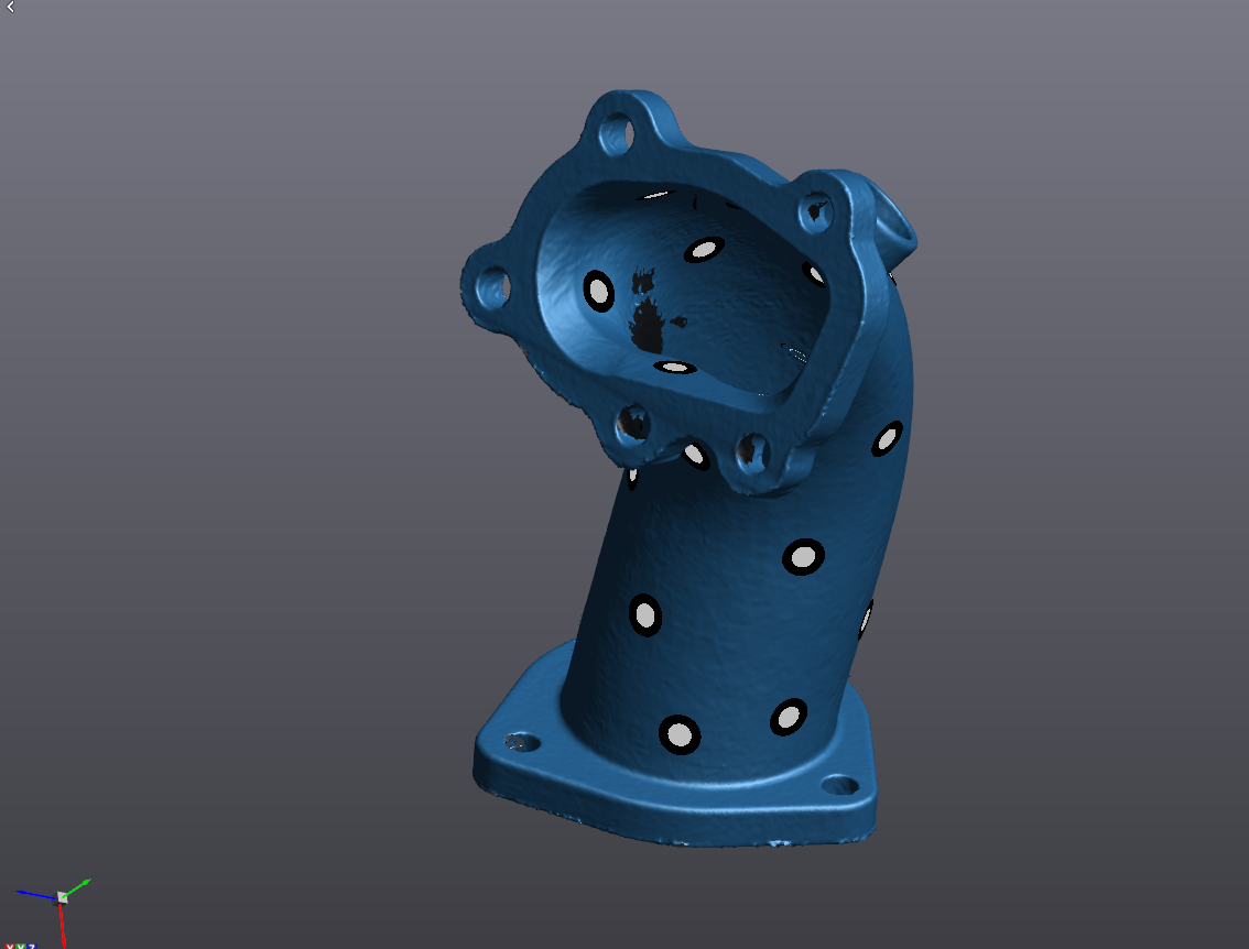
In the first part of this two-part post, we will take a look at the step by step process required to take a physical part sitting on your desk and make a digital copy you can 3D print. The model we will be looking at is this pipe.
With its unusual bolt pattern and organic routing, this part is an ideal candidate for reverse engineering via 3D scanning as doing so via manual measurement methods would prove extremely difficult and inaccurate.
We will begin with our scan already acquired (we are just looking at post processing here, not scan acquisition). As we can see, we have a relatively complete scan, but there are definitely some holes present, and almost certainly a few mesh errors hiding in the surface.
For this process, we will be using Creaform’s reverse engineering software module, VXModel.
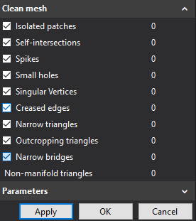
First, we need to heal errors and imperfections in the mesh using the remove spikes and clean mesh functions.
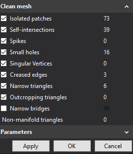
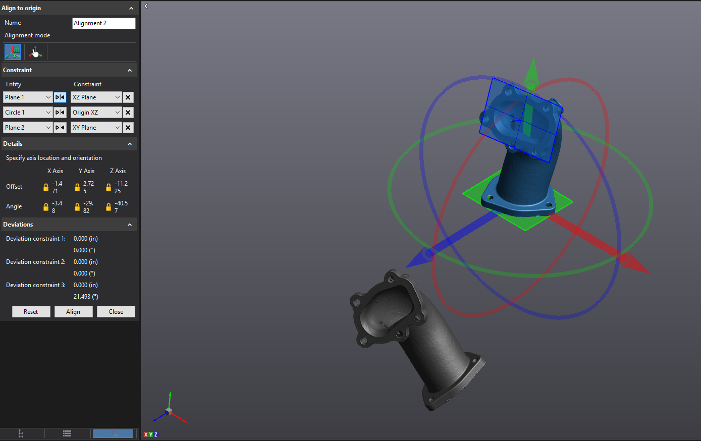
Once our mesh is free of these microscale errors, we need to turn our attention to the macro errors. But first, it is always best practice to create an alignment for our mesh that makes sense for our application. We will do this using three datums, two planes, and a point.
Here we can see our old alignment and our new alignment side by side. The new one is much more CAD friendly.
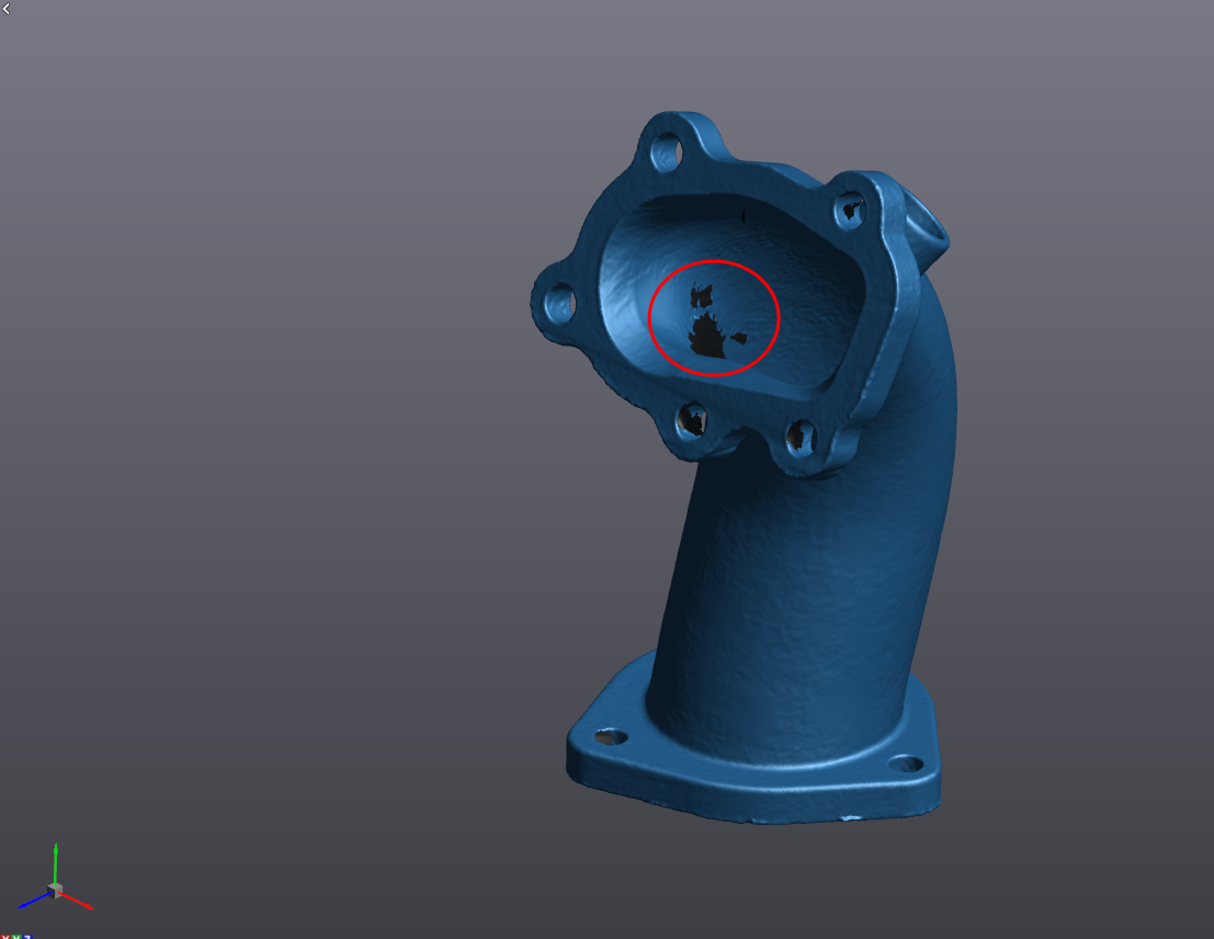
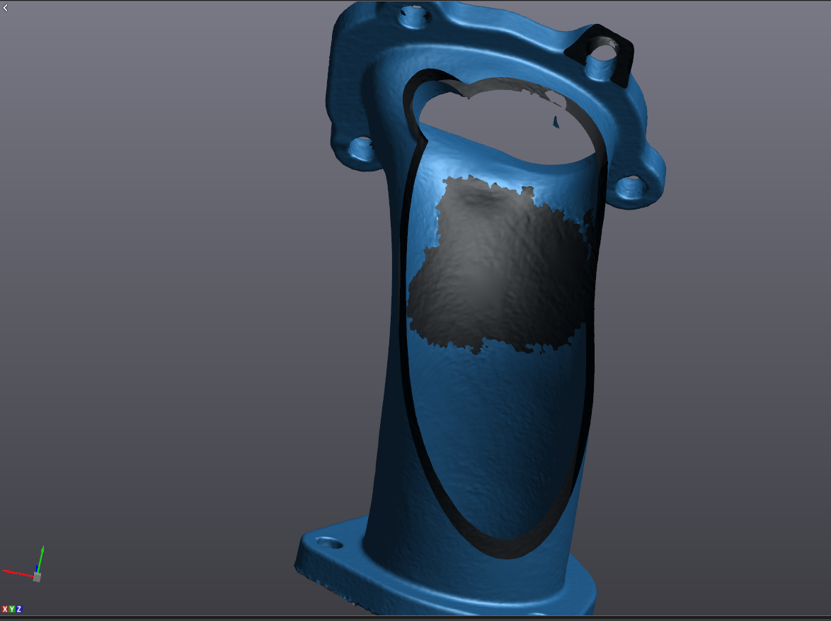
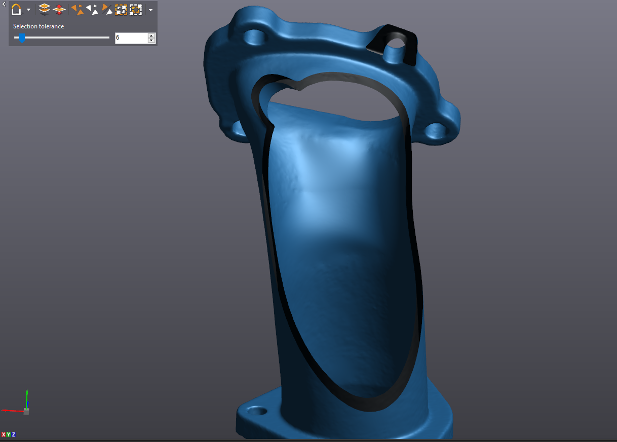
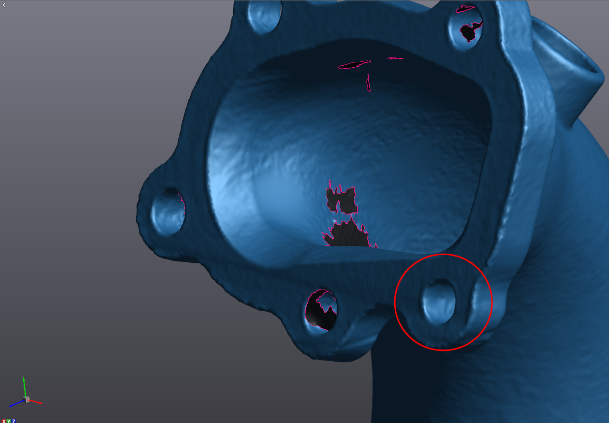
Now we have a nice alignment, but we don’t have a watertight mesh. We’ve got some holes where we were not able to see with the scanner. For the large internal holes, we can use a clipping pane to see better inside the part.
For larger holes like this, it is good practice to clean the boundary and use the partial hole fill function as opposed to the full hole fill. Biting it off in smaller chunks reduces processing time and risk of error.
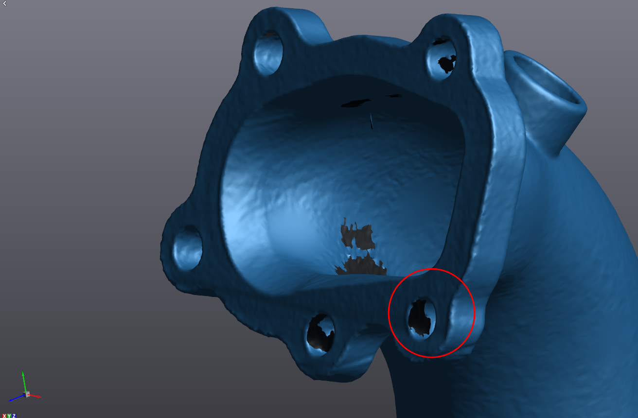
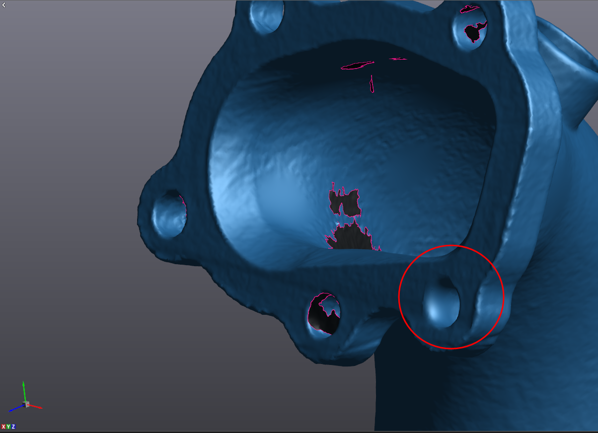
From there, we can work our way around the part filling holes as we go. For holes in areas where the surface curvature is consistent, default hole fill settings are fine, but areas like sharp edges we need to tweak our settings to avoid destroying the crispness of the edge. We can do this by simply turning the Smooth Boundary Layers option down to 0 (vs a default value of 3).
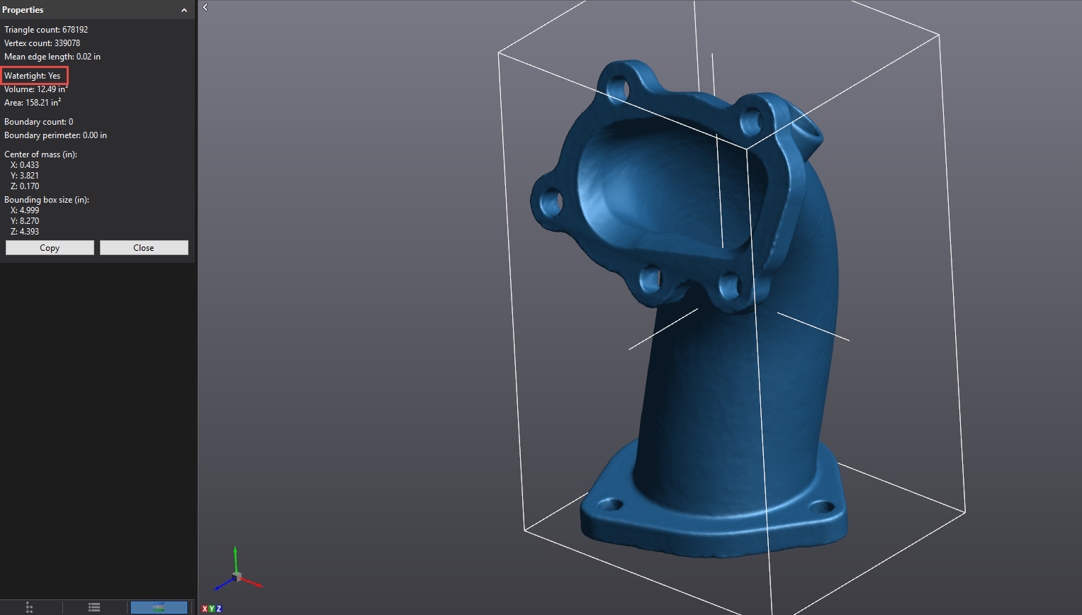
Once all holes are filled, we can run another mesh cleaning to take care of any anomalies we may have accidentally created while filling holes. Now we have a watertight mesh.
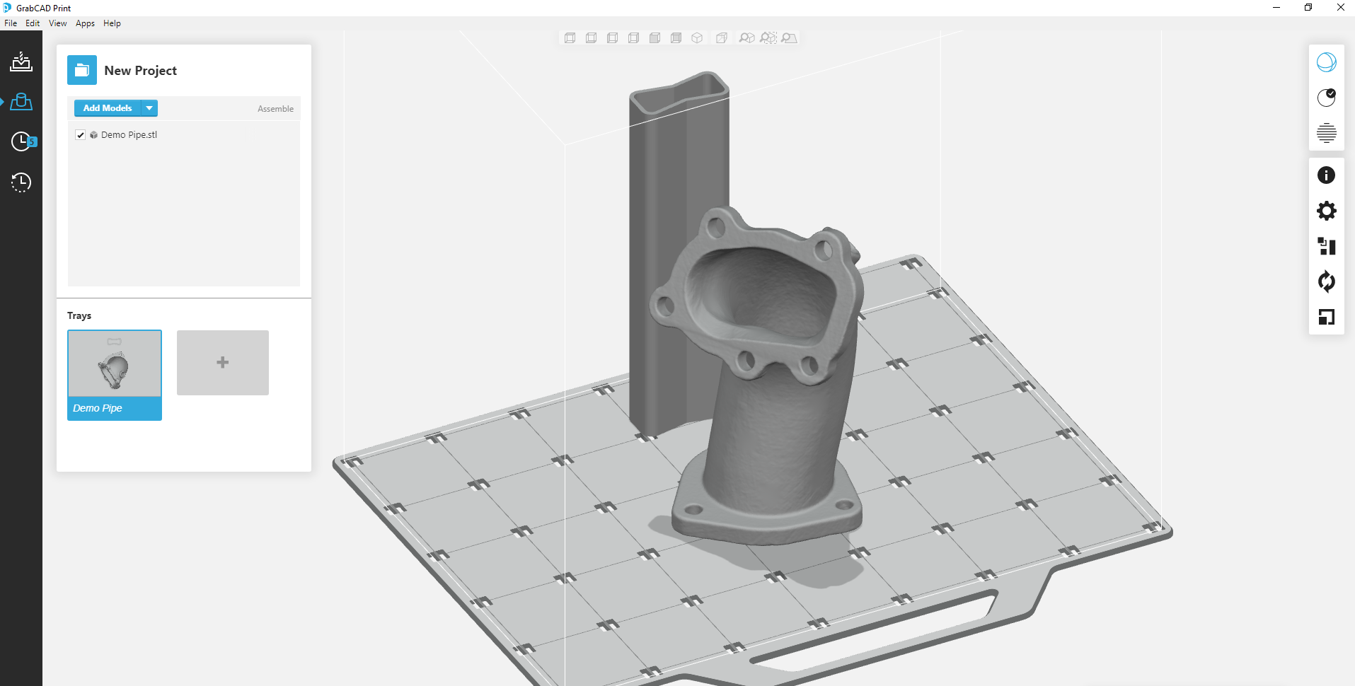
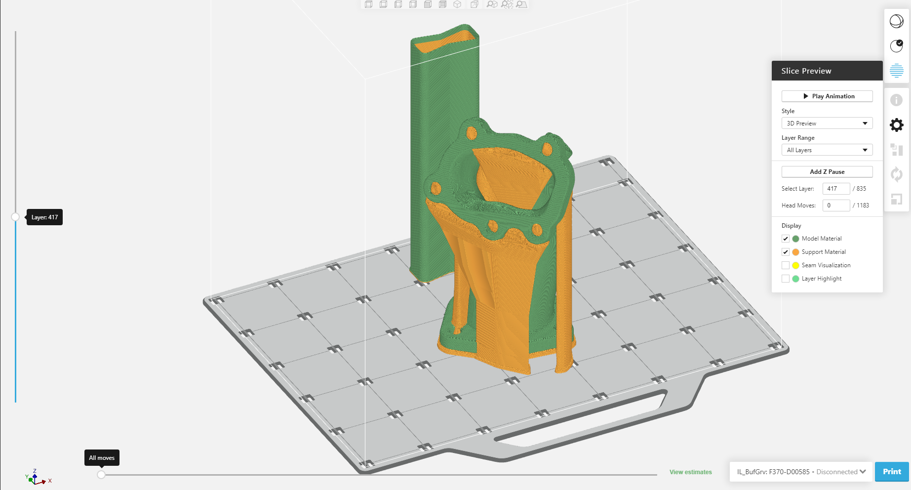
From here it’s a very simple export -> Mesh and we are ready to 3D print.
Stay tuned for part two where we look at getting a parametric CAD file from this scan as opposed to just a mesh STL file as shown here.
Cullen Williams
Application Engineer
Computer Aided Technology, LLC

 Blog
Blog 