Connection Labels: Extra Info in Your Schematics
SOLIDWORKS Electrical has a nice tool for displaying the connections to a component, through the use of the Connection Labels command. A connection label is simply a symbol that looks like a table and contains a multitude of attributes. It is frequently used similarly to what is shown below, as a means of displaying the destination for each wire on a connector.
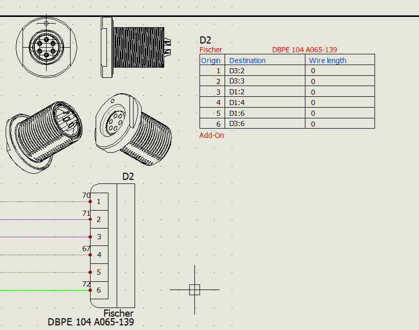
Something that I’ve seen that is a pretty neat idea, is to take those symbols a step further and add connection points. Rather than having symbols connected, with the tables off to the side, you can just use the tables as the symbols themselves, containing attributes for the wires, so that you have a drawing that kind of looks like a harness drawing except it is less mechanical and more electrical.
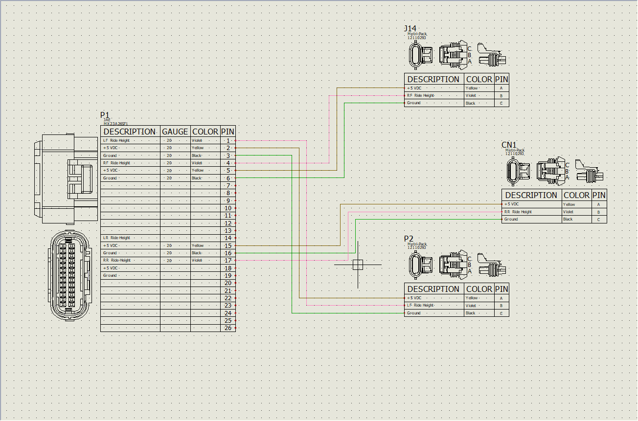
Of course, there are many attributes you can choose from to put in those symbols so that it displays the information you deem important. My first example has attributes for the wire destination. My second example was information about the wires themselves. You can include the wire length, wire mark,…I counted 45 different attributes I could place, so there’s a good possibility that what you need is there.
Brian Cooke
Application Engineer, Electrical
Computer Aided Technology, LLC