SOLIDWORKS - Multiple Parts In a Single Drawing
The standard method for documenting your design is to create a drawing file for the assembly, and several other drawing files for each individual component. Alternatively, it may be ideal to have the component information contained as separate sheets in a single drawing file. This method is more common with smaller assemblies but could also be scaled up and applied to larger ones. With this approach, you might have the assembly shown on the first sheet and the various components on the subsequent sheets. One issue you may encounter with this method is the incorrect information appearing in the drawing title block for the component sheets. In this scenario, the title block properties of the drawing will likely show information related to the assembly and not these individual components. This can be caused by the title block annotations and the source that they are linked to. These incorrect notes can be easily avoided by adjusting your drawing sheet formats. Let’s look at how we can alter those sheet formats to work for this scenario.
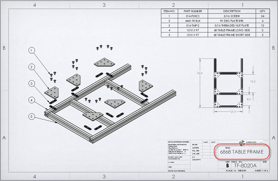
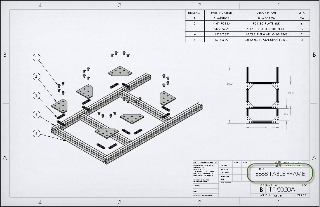
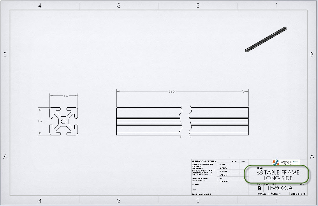
In this example, we have a frame assembly made up of standard aluminum extrusion, some plate brackets, and screws. We could create individual drawing files for each component and end up with a total of 6 drawing files. Instead, we will create a single drawing that contains the assembly information on the first sheet and each additional sheet will represent component information from the different part files.
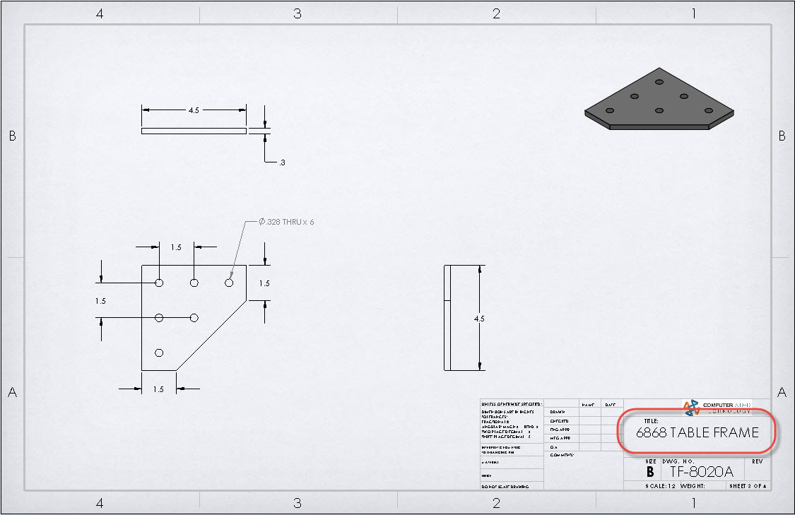
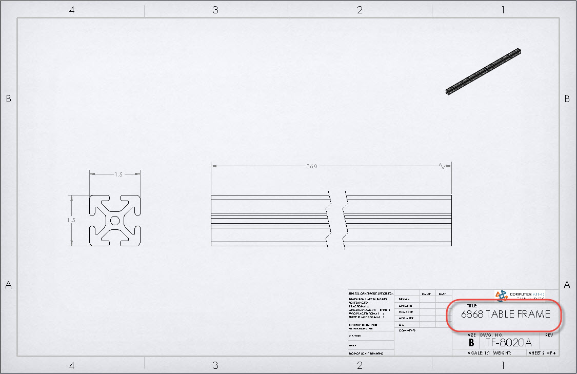
In order to simplify this example, we will focus on the first 3 sheets of this multi-sheet drawing. It was created using one of the standard sheet formats. The “Title” field of this drawing is linked to the “DESCRIPTION” custom property. Our problem is that it shows the same information on every sheet. This value of “6868 TABLE FRAME” happens to be the main assembly’s DESCRIPTION.
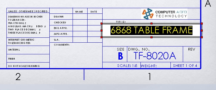
This would not be an issue if each component was going to be detailed in its own drawing. The annotation is currently linked to the “DESCRIPTION” custom property of the referenced document. Specifically, this is called out by the syntax “$PRPSHEET:”DESCRIPTION”” This means that the “DESCRIPTION” custom property is being pulled from the file that the drawing references. The problem is that the drawing identifies only 1 document as the referenced file to pull the property from. This happens to be the file that was placed in drawing’s initial view. In this example, the assembly was placed in the drawing first. This causes every sheet to pull the “Description” property from the assembly file. Again, this works great when only a single file is being shown in the drawing. This is only a problem in our specific scenario where we wish to have different components on each sheet of the same drawing.
To make this function as desired, we need to change the note’s property link to pull the custom property from the specific part that is shown on that sheet. Luckily, this is an easy task.
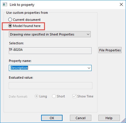
1. Edit the Sheet Format and select the note in the title block that links to the filename property.
2. Change the custom property link to “Model found here”.
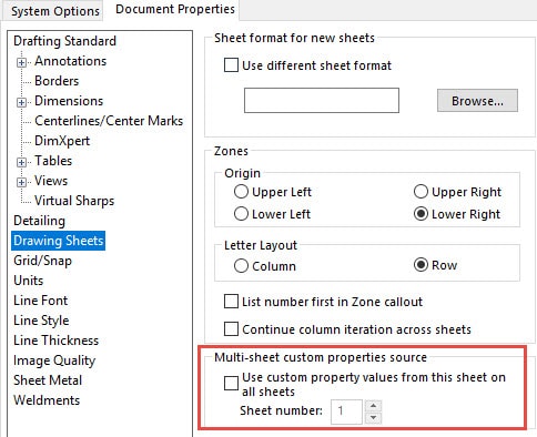
3. In the settings for the “Document Properties” Clear the checkbox for the option “Use custom property values from this sheet on all sheets”.
4. Save this sheet format and use this same format on each sheet. Each sheet will now automatically update the Description in title block according to the model that you insert into that sheet. You can also go a step further and save your drawing template with this new sheet format.
Here is the updated version of the previous three drawing sheets.
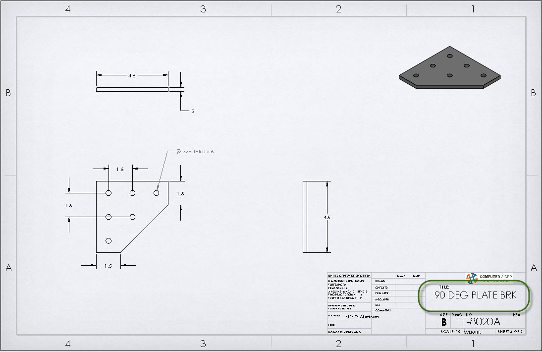
Notice that each sheet has the “DESCRIPTION” value correctly linked to the part being displayed on that drawing sheet. Now, this single drawing is behaving more like what we would see if we created a series of drawing files, one for each component.
Greg Buter
Senior Application Engineer
www.cati.com