Using the Freeform Tool for Real Design
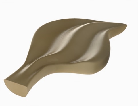
If you’ve taken the SOLIDWORKS Surface Modeling class you’ve been exposed to the Freeform tool. During the case study, you were shown how to use the tool to modify the surface of a leaf-shaped extrusion to give a more natural appearance. Now seriously, how often are you going to be modelling leaves that look like this?
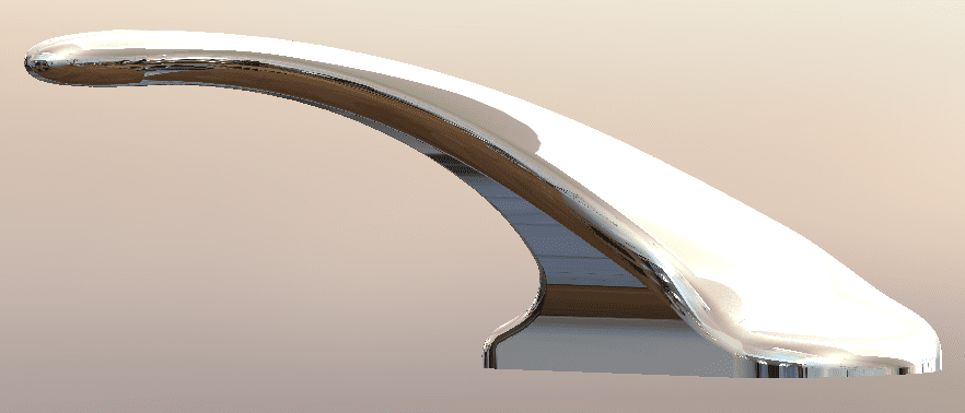
I’d like to show you how to use the Freeform tool in SOLIDWORKS to make changes that are simple and elegant, as well as useful for modeling real products like this.
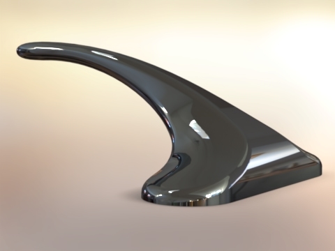
By looking at this faucet model you’d think I used complex curves, Lofts, Sweeps, or Boundary features; but this is what my Feature Manager Tree looks like.
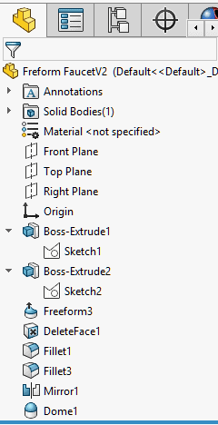
Most of the work was done with the Freeform feature.
Before I show you how this was created with the Freeform tool, I want to give you some tips for managing your shapes with the tool.
The Freeform feature tool allows you to convert surfaces and their edges into 3D splines and then adjust the shape and curvature using those splines. If you’ve worked with splines you will understand how easy it is to lose control.
Guidelines for Manipulating Splines & 3D Splines
- Use the control polygon rather than the handles. The changes can be more subtle and end with making a much smoother curve.
- Use the triad handles when adjusting the polygon vertices. It will keep the adjustments in a single direction.
- Work with as few spline points as possible.
- To keep your curves smooth use the least number of control vertices.
- Use the viewports or work within orthogonal views. This will keep your curvature adjustments from moving in a direction you can’t control.
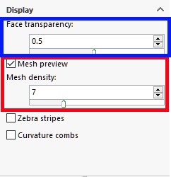
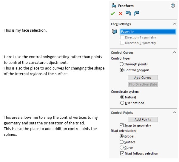
Now, let’s look at the tool properties:
I have split the dialog to more easily explain the controls. This is the lower part of the dialog and it controls the visibility of the face and curvature of the modifications. For this example, I will only use the Mesh preview and set the Face transparency to .5
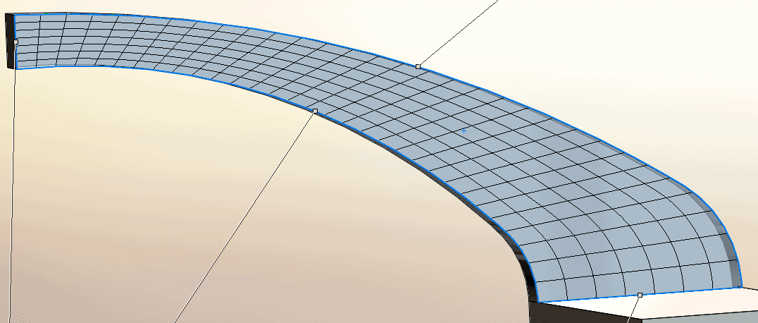
This is what the face looks like before any modifications, using these settings.
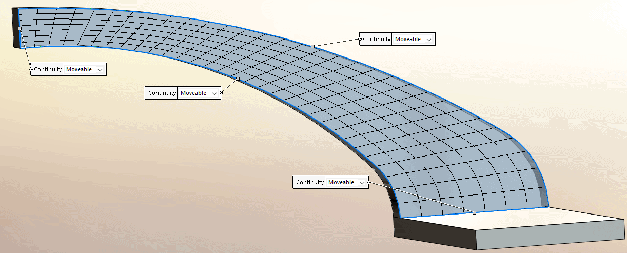
After you select the face to modify, SOLIDWORKS will allow you to set the Continuity flags for each edge. For this example, I have selected “Movable” for all edges. See SOLIDWORKS help for more information on Continuity settings.
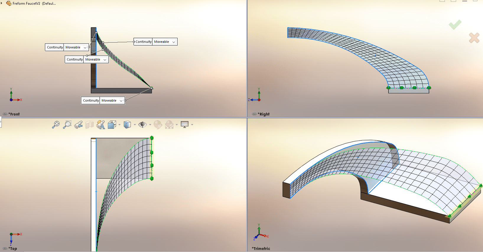
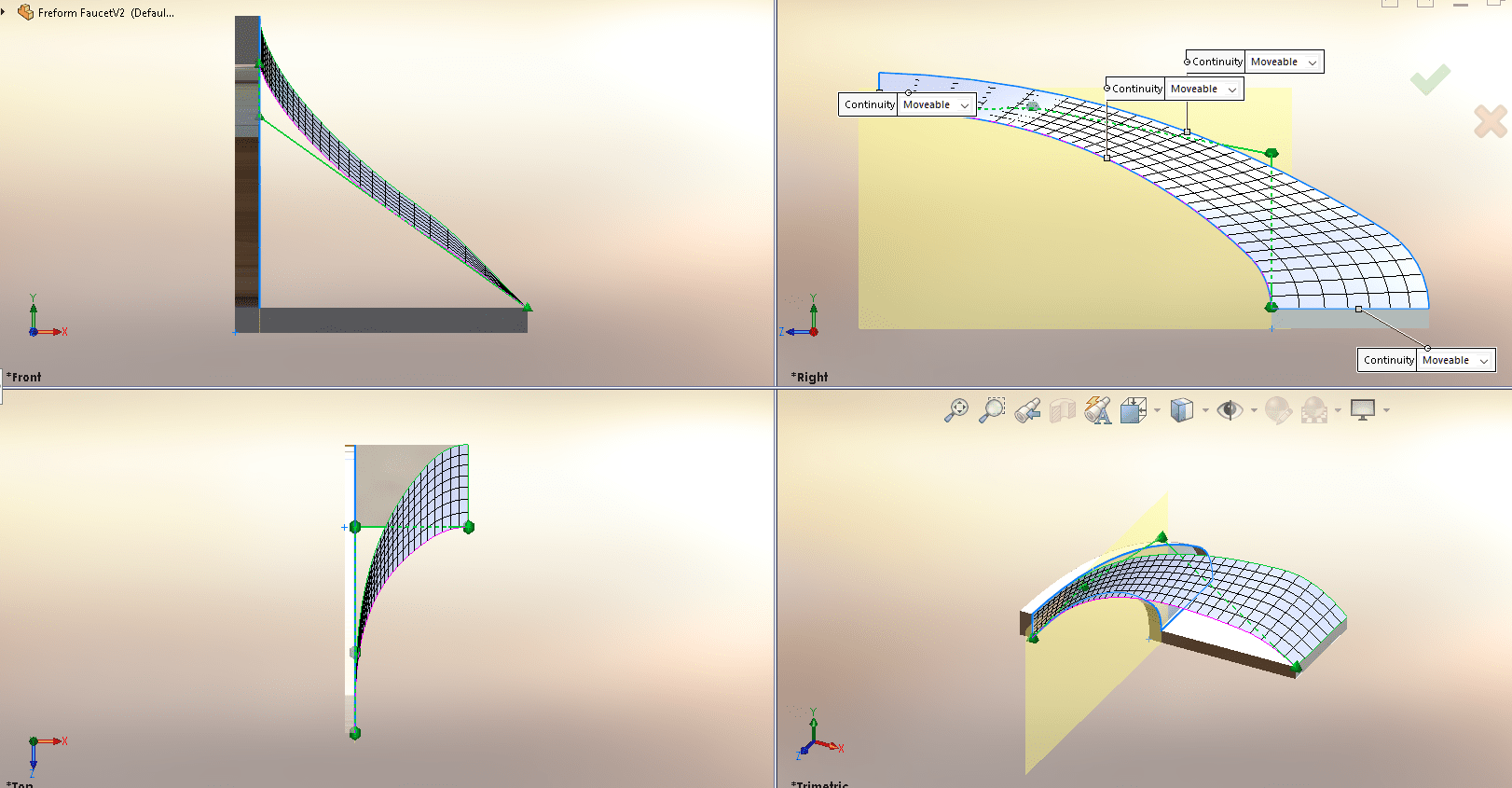
I have selected these settings in the dialog for my first adjustment.
When I select the first edge to modify there are four points.
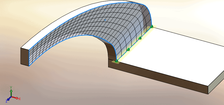
By using the four view, Viewport I can zoom in and move all the points to the outside edge of the model.
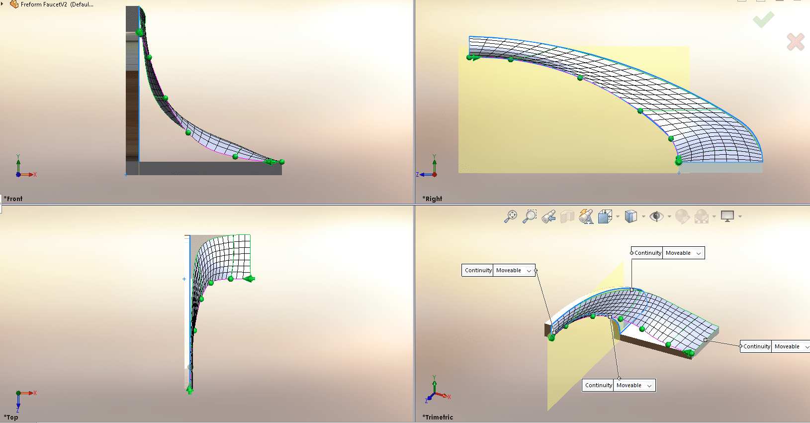
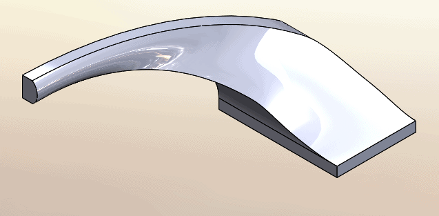
After moving the vertices and control points to the new edge and completing the feature this is what the part looks like.
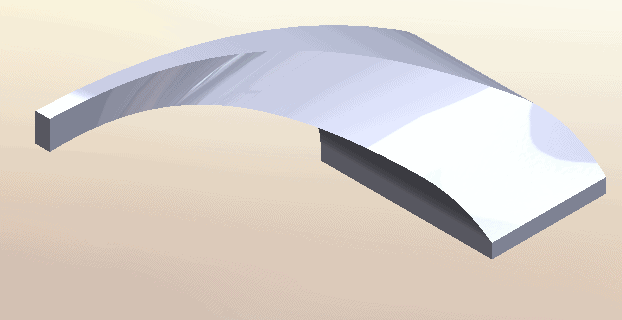
Not bad, but I would like to improve the transition so it’s not so bulky. This means adjusting the trailing edge.
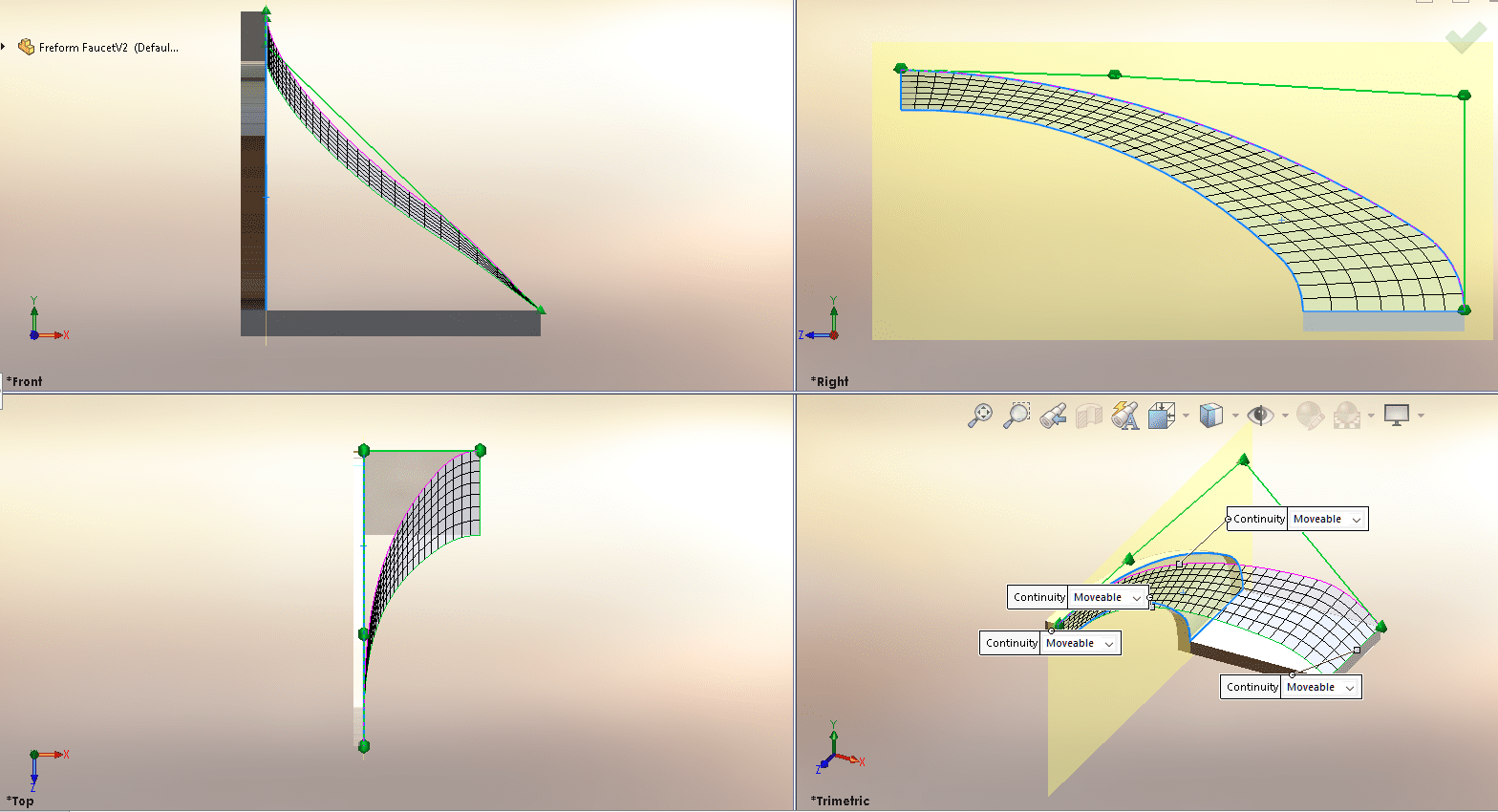
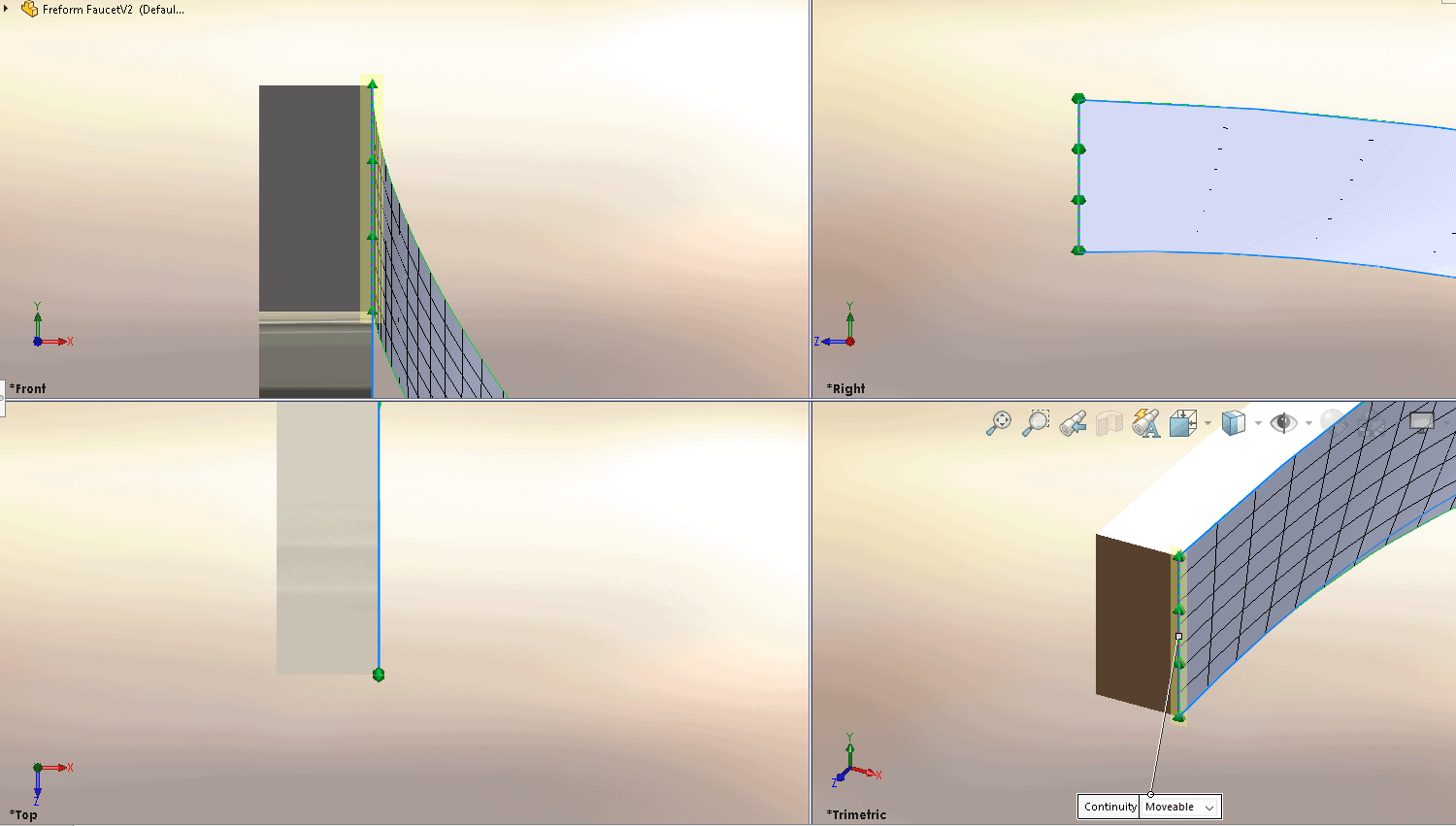
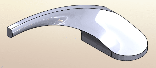
From this:
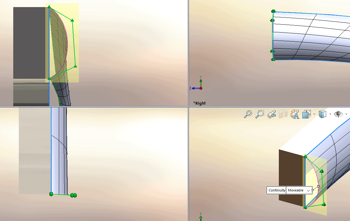
To this:
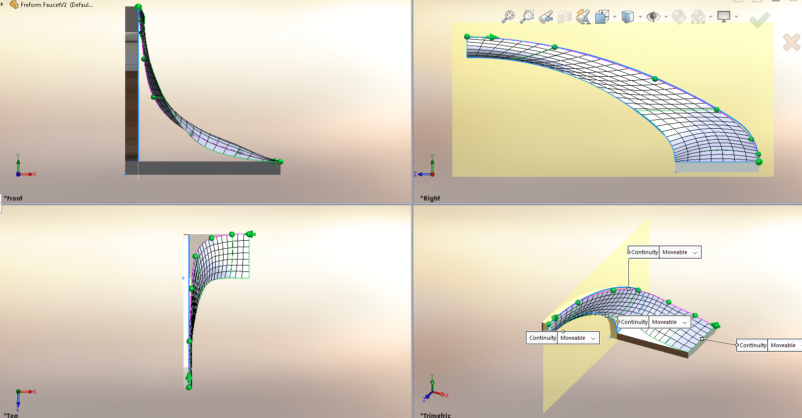
I have added control points using the “Add Points” button and then manipulated them to make a smoother curve.
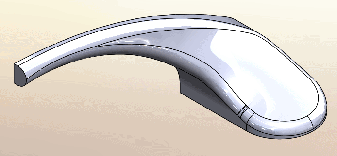
For the leading edge, I did the same thing.
From this:
To this:
The last modification was to the front-top edge, to add a rounded end.
Result:
The solid now looks like this.
Next, I added a full round fillet to the base.
Then another fillet, this time, symmetrical with a circular profile.
By mirroring the body, I achieve symmetry.
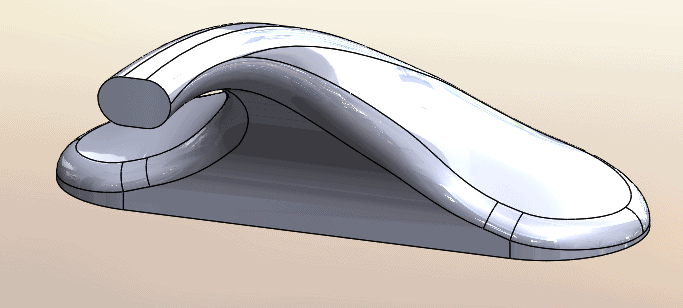
The last feature is a Dome. Then, by setting the display to shaded and adding a Chrome appearance I get an actual fixture.
I hope this article has given you some insight into a new way to manipulate your designs using the Freeform Feature.
Dennis Barnes
Application Engineer
Computer Aided Technology, LLC