Advance FDM Mode Lesson 2: General Tour (Part 3 of 4)
Welcome to the third part of our step-by-step walkthrough of the “General Tour of GrabCAD Advance FDM Mode” series. In this section, we will dive into the core that makes up GrabCAD – Advance FDM Mode. Let’s dive right into the powerful Selection Menu and it’s sub tabs of Body and Face. Starting with a blitz through “how to get there”
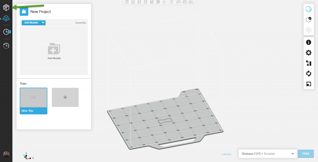
Launch GrabCAD
Once on the landing page, be sure to click on the 4th Icon to get into the Advance FDM mode tab.
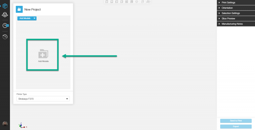
In order to use anything in the Selection menu, you have to import a part.
I would recommend a part file with multiple part bodies in it. (Details on file types can be found here)
Set your print settings and orient the part for printing before exploring Selection Settings.
Once we start changing infill settings, the slice time will increase a lot if the part is not properly oriented for Part 4.
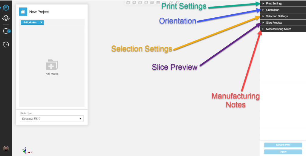
Welcome to the Selection Settings Menu:
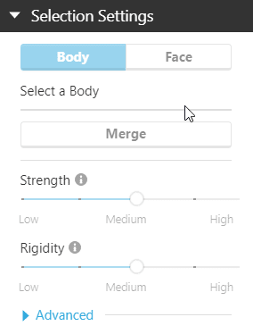
The default active tab is the Body tab, note its a toggle switch. So only Face or Body can be actively selected at any one time.
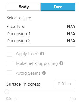
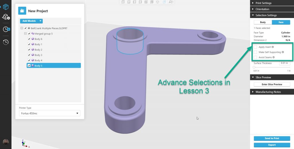
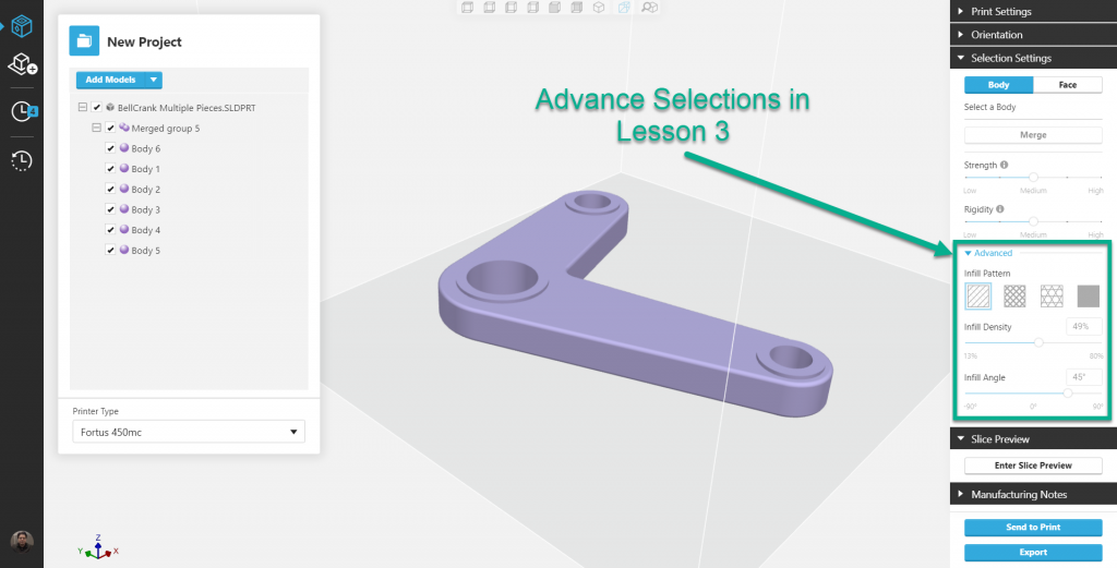
Note: The Advance Options under the Selection Menu will be covered in Lesson 3, Parts One and Two.
Please ignore those features for the purposes of this walkthrough.
Starting with the Body Tab:
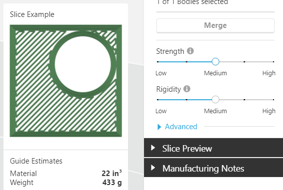
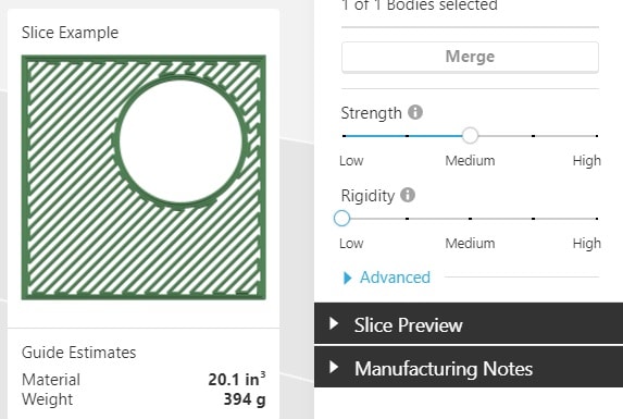
we will explore 2 methods of changing the properties of the parts through the use of the “strength” and “rigidity” sliders. Note: The default setting for both Strength and Rigidity is Medium.
Standard/Default – S & R
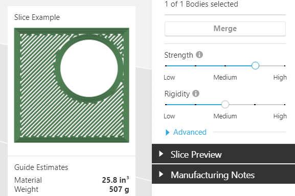
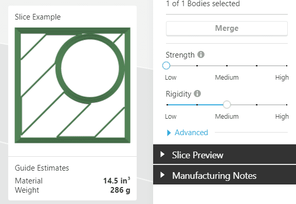
Low vs High Strength
The difference between a High Strength and low Strength part is the amount of Infill. (Note the Percent of Infill is covered in Lesson 3) See the examples below for a visual, and note High Strength prints as solid.
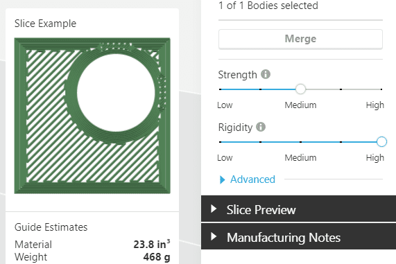
Low vs. High Rigidity
Rigidity is the number of contours/shells a part has. That is to say, it’s the full perimeter wall thickness. See examples below for a visual.
Default Settings with few changes:
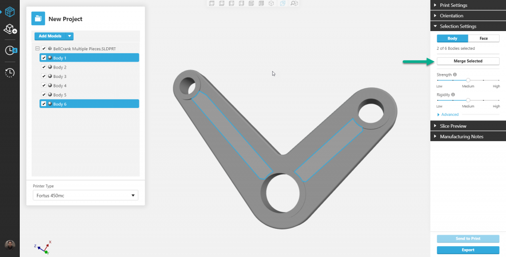
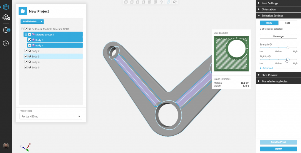
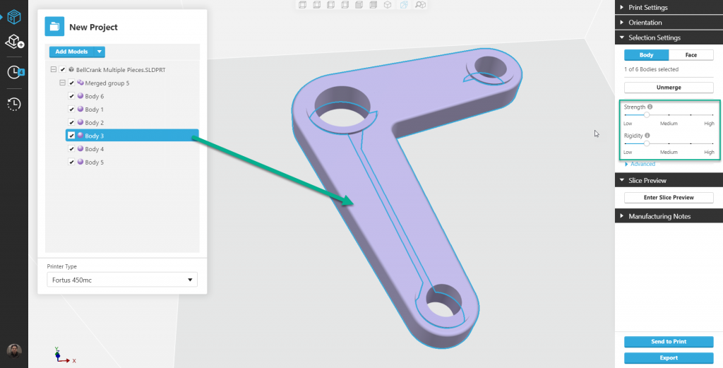
By selecting one or a couple of bodies, we can use the merge body tool to combine them into a group. Then apply new Strength and Rigidity to that subgroup while the overall group parameters remain the same.
Select 2 Bodies & Click Merge Button
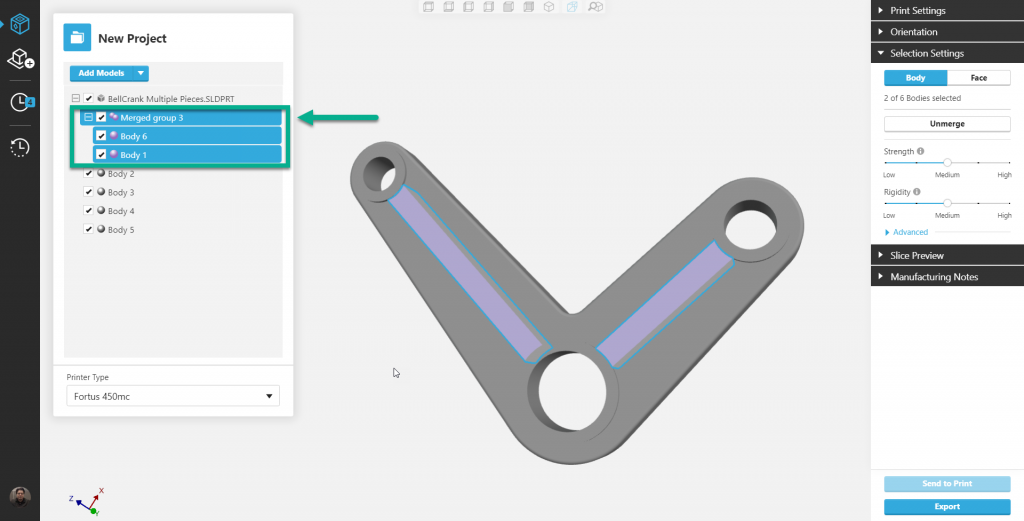
Notice the pair of bodies are now paired under a merged heading.
Note: you can create more merge groups too.
Notice the pair of bodies are now paired under a merged heading.
Note: you can create more merge groups as well.
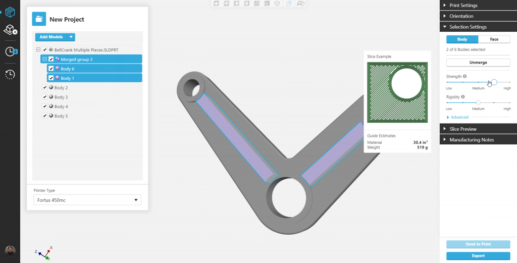
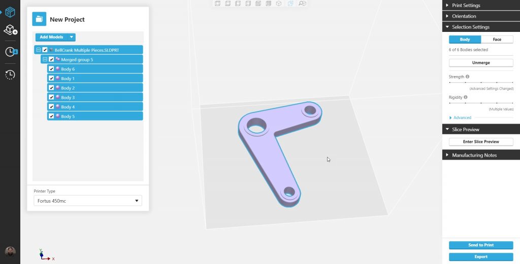
Changing the Rigidity and Strength of this merged group will not affect the rest of the part.
Note: can select individual bodies too and change their rigidity and strength as well.
New Settings with a few body changes:
Using this method we apply new general parameters to the entire group. Then dive back in and change the strength and rigidity of individual bodies.
Select all the bodies and merge them into a single group.
Edit the Strength and Rigidity to your new print setting standards.
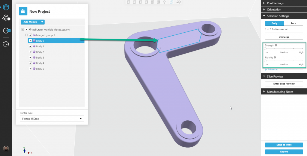
Now select one of the bodies and edit the strength and rigidity.
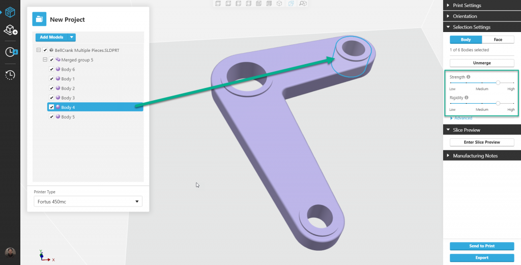
Select another body and change the Strength and Rigidity.
Change another part’s Strength and Rigidity.
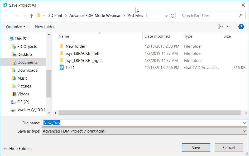
Now Save the project to pick up with part 4 of 4 later or proceed with part 4 of 4.
In the final part of Lesson 2, we will explore all the changes that occurred to the bodies we edited.
Keith Weber
Application Engineer for Manufacturing Solutions
Computer Aided Technology, LLC
Advance FDM Mode: General Tour
1 of 4: General Menus & Add Models
2 of 4: Print Settings & Orientation Menus
3 of 4: Selection Settings Menu & Face and Body tabs
4 of 4: Slice Preview Menu and Manufacturing Notes