GrabCAD Toolpaths vs. GrabCAD Advance FDM Mode Toolpaths Part 1 of 2
Toolpaths are the machine’s movements that build the parts we want, either in subtractive or additive technologies. One of the key differences between additive and subtractive methods is the porosity of the created part. Porosity is the number of voids by volume in any material. Most if not all subtractive processes (while using the same 3D printable materials like ASA/ABS) will result in non-porous parts.
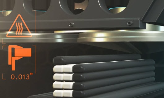
However, due to the FDM nature of additive technology, the parts created will be porous. The porosity from FDM 3D printers is built into the foundation of the 3D printing technology. Local geometry makes it difficult for toolpaths to fill in all the nooks and crannies since stacking equal bead widths on top of each other inherently creates a small 4-pointed star shaped air gap. As more layers are added during the printing process, more gaps are formed. The porosity of the part is strongly correlated with its strength. The less porous the part, the stronger it is.
Let’s take a deep dive into the settings of GrabCAD vs GrabCAD Adv. FDM mode. (Note: Insight is tabled for this GrabCAD self-reflection)
Before any 3D printer starts the build process, the part needs to be sliced. Whether processing CAD data or STL files, GrabCAD generates slices or layers which then creates toolpaths to fill an area based on your settings. Your settings will determine the porosity of the final printed part.
Early GrabCAD Print:
Note: Until recently, the types of parts that could be printed was limited. There were many demanding applications that would require the strength of a solid in one area, but it could be more porous in other parts of the build. This led to a lot of parts having to be built on separate build trays using different settings and then had to be assembled together. A post-process to combine the parts together required additional time, labor, materials, etc.
Current GrabCAD Print:
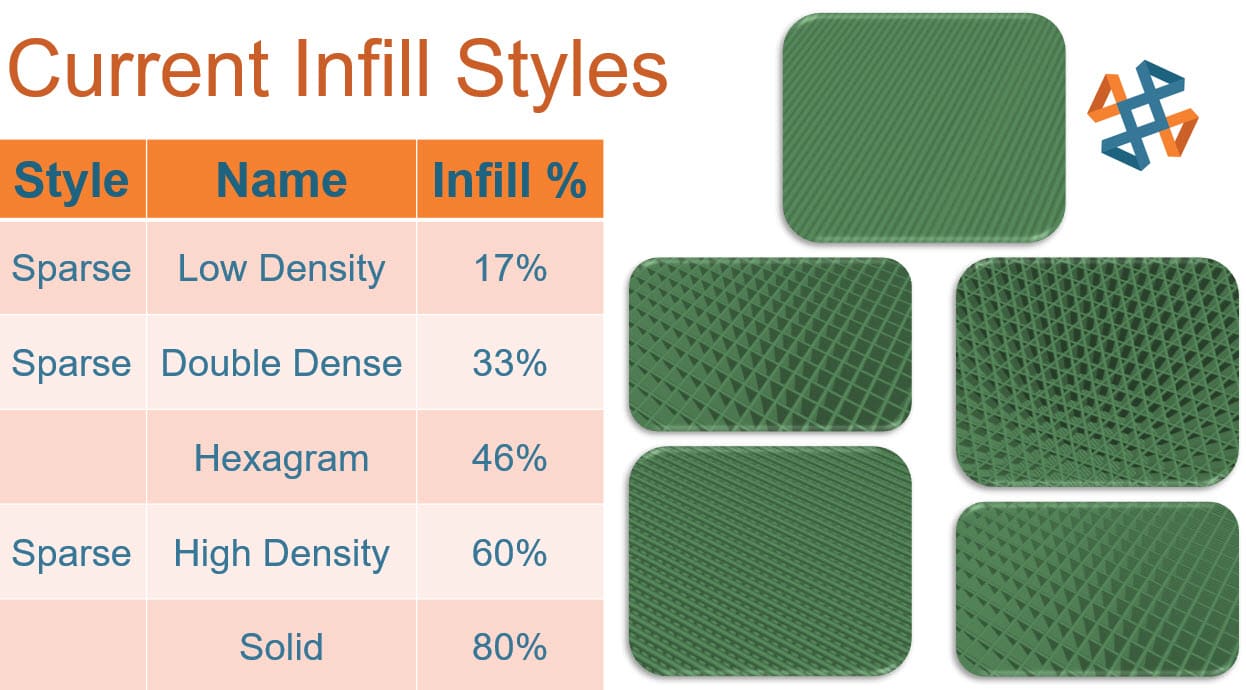
Having learned from Stratasys’ years of experience in nearly every field imaginable. Their engineers have been doubling down on their efforts for 3D printing software mastery. Currently, GrabCAD offers 5 default infill styles, which broadens the number of applications we can use the same materials in.
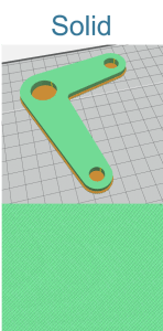
Selecting the appropriate infill style is the first step in affecting our porosity and subsequent strength. Changing a (17%) infill to the “solid” at (80%) has a large effect on the porosity and strength of the part. It increases the density of the printed part just over four times.
Is printing a solid part every time worth it?
The time to complete each print is drastically increased with the higher infill, and so is the cost of material. The desire for additional strength must be aligned to the time and money constraints, which means that sometimes the lower infill part will be more beneficial for the business.
What about re-working the part: Say if the part has some load-bearing areas but the rest didn’t require the extra strength?
The complex load-bearing area could be printed in solid then later post-processed into a working assembly of other materials to lessen the cost. However, this process increases the complexity of the design, the time needed to complete, the need for communication and labor.
Compromising on strength and using a middle ground?
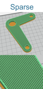
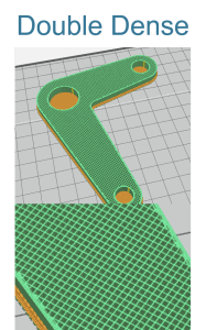
In the interest of time and money, a lot of companies find a middle ground while setting rules for printing in order to conserve printer hours and material usage. This means that they generally must decide between double dense or hexagram infill method.
What about organic or ergonomic shapes; what’s the best way to choose?
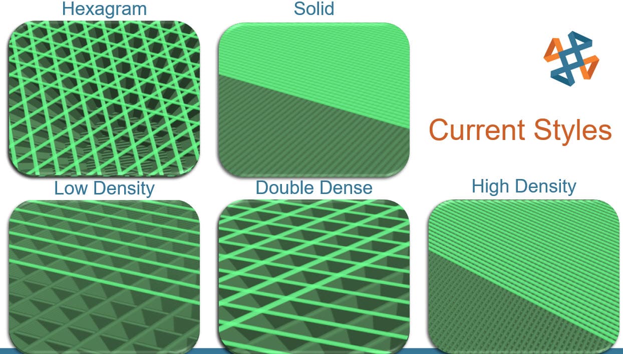
Each of the 5 current styles of infill has its strengths, due to the way their toolpaths intersect with the contours of the part and themselves. Note low density, high density, and solid are all the same linear toolpath that prints in one direction layer A, then at a 90-degree perpendicular on layer B. The only difference in those 3 infill methods is the variable gap between the roads. While double dense and hexagram overlay roads on top of each other in the same layer.
But even with these different toolpaths, there are some applications that are not fully served by these options, since the options are very linear. So, in an ever-changing world, more infill options are needed.

GrabCAD – Advance FDM Mode:
The magic 4th Icon:
There are rumors about Adv. FDM mode being able to replace Insight, however Adv. FDM is missing some features and others are not fully deployed yet. So only time will tell if Adv. FDM will truly be able to replace Insight.
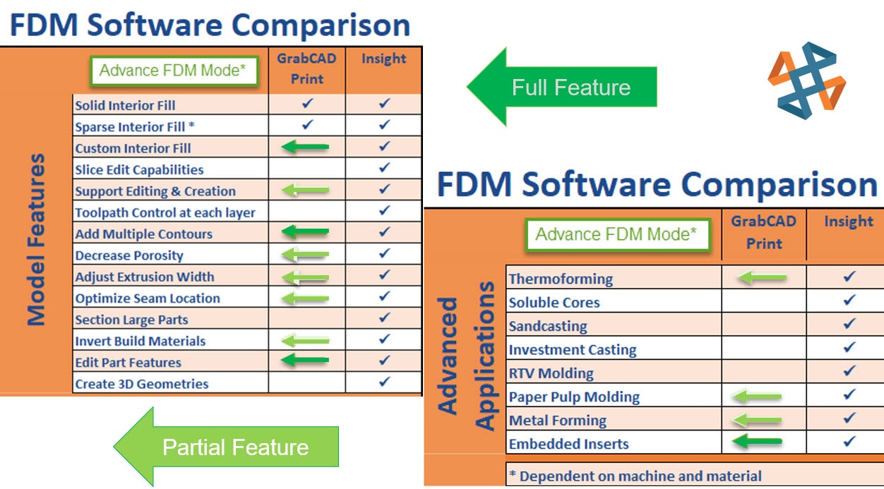
Dark green: Features fully implemented; Light green: Features partially implemented.
In the Adv. FDM mode world:
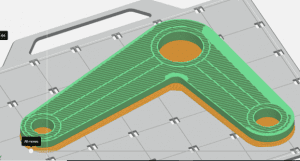
Look at the image below. Would you be able to accomplish this using a single infill method?
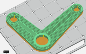
Can you spot the differences in the infill method?
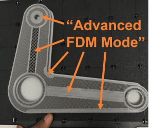
Multiple infills, living in harmony, working as a team to deliver strength and reduce porosity wherever needed. All infill types printing at the same time within each layer, without the need for post-processing.
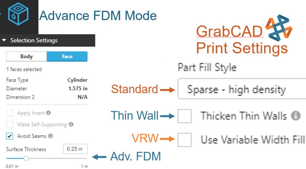
Using GrabCAD Advance FDM Mode’s separate tab enables the modification of CAD data. (STLs can’t be used in Adv. FDM Mode) Changing the infill type of different CAD bodies or geometry faces makes the part better suited to its custom function. Then all that is needed is to send the newly sliced file over to GrabCAD for printing.
Strengthening one area, lightening others, or even thickening a single wall, to resist grinding/impacts it will receive, are now possible and extremely easy to do within the same build. When compared to designing an assembly of parts that would need to be assembled after multiple prints completed, among others, you save time, money, material, and labor.
Using Z – Pauses enables the user to drop in metal rods, bushings or nuts to strengthen mounting areas while in process. (Note the GrabCAD Z-Pause is not as robust as Insights). To learn more about what is Advance FDM mode and how to use GrabCAD Advance FDM mode follow the links below:
Advance FDM Mode: General Tour
1 of 4: General Menus & Add Models
2 of 4: Print Settings & Orientation Menus
3 of 4: Selection Settings Menu & Face and Body tabs
4 of 4: Slice Preview Menu and Manufacturing Notes
Getting Started with GrabCAD – Advance FDM Mode
Part 2 Sneak peek:
GrabCAD Toolpaths vs. GrabCAD Advance FDM Mode Toolpaths Part 2 of 2
Keith Weber
Application Engineer
Computer Aided Technology, LLC