SOLIDWORKS – Working with Circuit Board Files
Large assembly performance issues are a topic that frequently comes across my plate while working support calls. Even though every assembly is different, and a company’s hardware and environments are all very different, there are some common patterns that can be seen whenever we work on large assemblies. Number of components, number of top-level mates, flexible subassemblies, number of appearances, level of image quality are just some of the most common factors that we look at.
Engineering designs require us to take all components into account when we work on a project. SOLIDWORKS, coupled with today’s high-powered workstations, give users the capability of modeling and including every nut, bolt, and washer required.
The introduction of SOLIDWORKS Electrical in 2013 and SOLIDWORKS PCB in 2016, we now have tools to work with the electrical portion of our designs. This means we are bringing in circuit boards and running wires to make sure everything fits, and nothing is overlooked.
I am sure you have all tried importing a circuit board file at least once, and I am confident I know how this went. NOT WELL! These files, regardless of the format that is used, often come in unclean. There are often thousands of surfaces and few solid bodies mixed in. The second major problem we see is missing faces. Lots of missing faces.
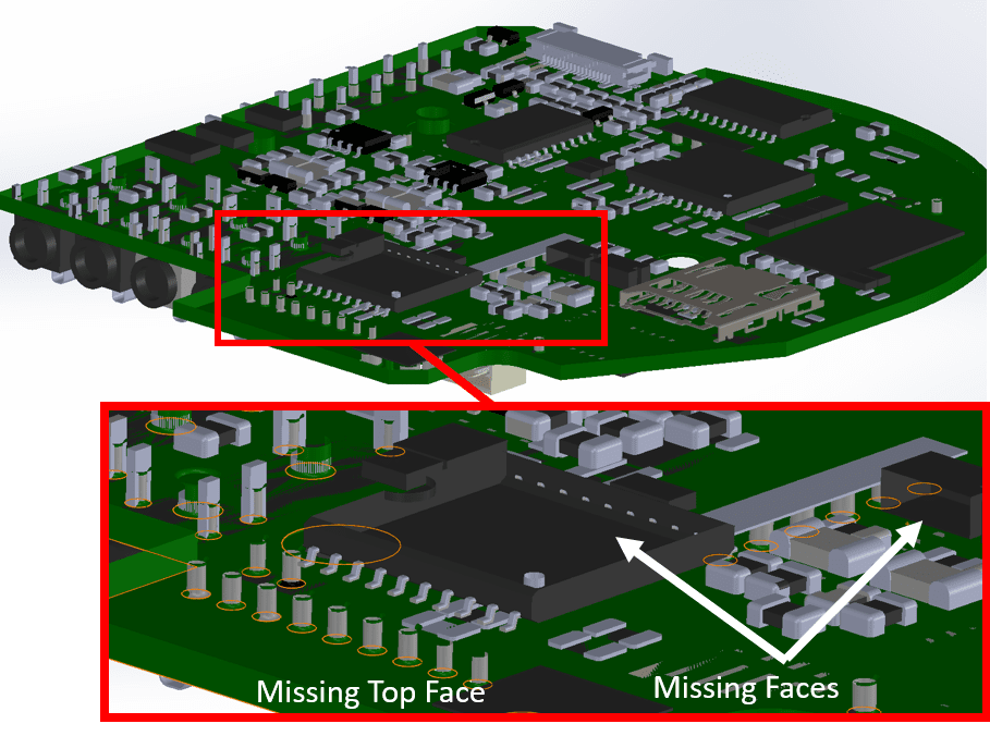
All of these missing faces cause large performance problems for us if we continue to use this model without cleaning up the geometry. This is obviously easier said than done! Many times there are too many faces to even begin manually patching the file. So let’s take a look at a very simple easy way we can get around this issue.
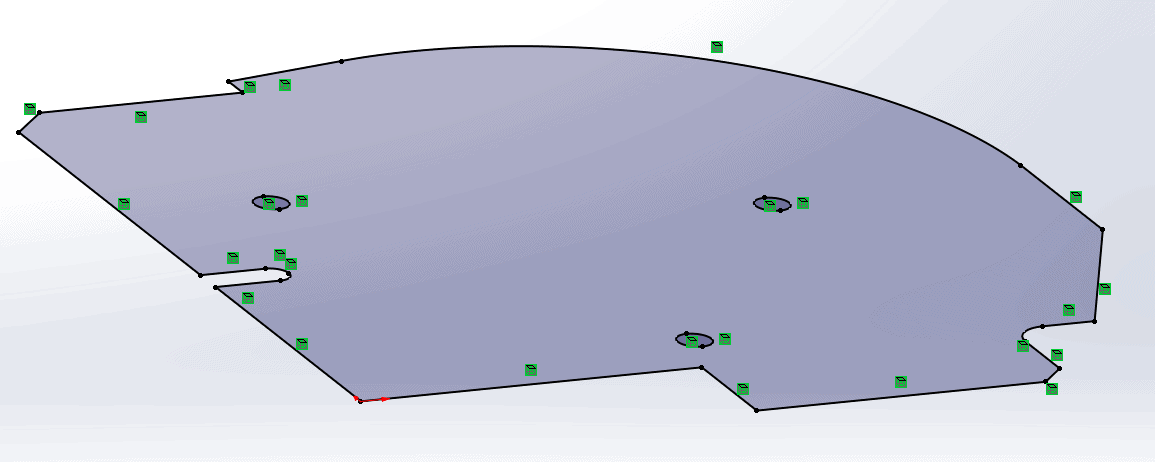
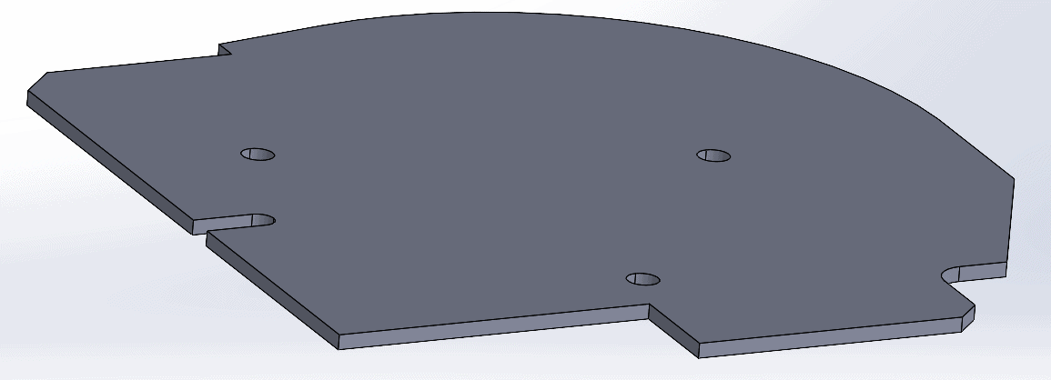
Step 1: Extrude a solid to represent the board. Include any major mounting holes or slot that are needed. Selecting the main surface and using convert entities is a good way to get the outside perimeter with very little effort. (You may want to copy sketch into new part depending on how larger your circuit board is)
Step 2: Hide this extrusion in your solid bodies folder and show your circuit board files again. Go to a top view. Use a screen capture tool such as the snipping tool built into Windows 10. Save the image as a jpg or png file. It may also be helpful to adjust the amount of ambient light to brighten up the image.
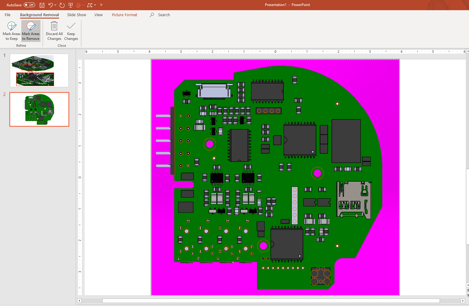
Step 3: Open the image in PowerPoint and use the remove the background tool to easily remove any areas that you do not want in the image. I will typically remove anything outside of the circuit board and any of the holes. (In the image below, anything colored pink will be removed when the image is saved)
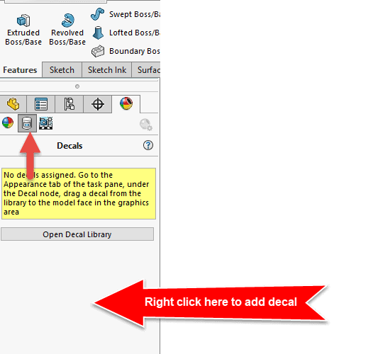
Step 4: Back inside of SOLIDWORKS, hide your circuit board surfaces and show the solid body of the board extrusion you created in step 1. Click the multi-color ball at the top of the Feature Manager and select the Decal icon. Right-click on the gray area of the Feature Manager to add a decal.
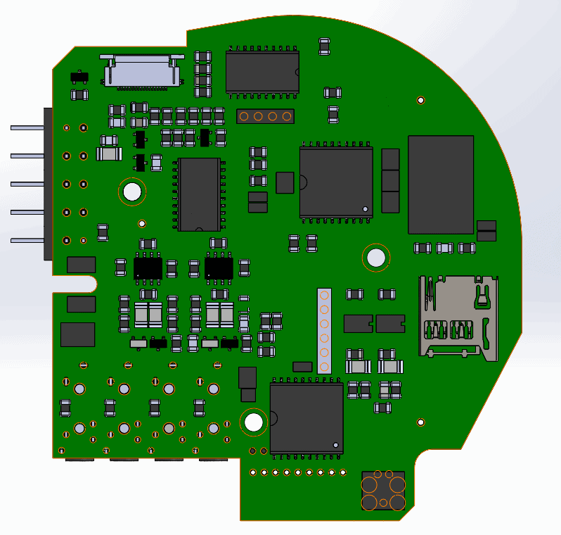
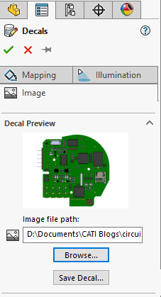
Step 5: Browse to the circuit board image file that was saved in step 3. Select the face of the extrude you want to apply the image to.
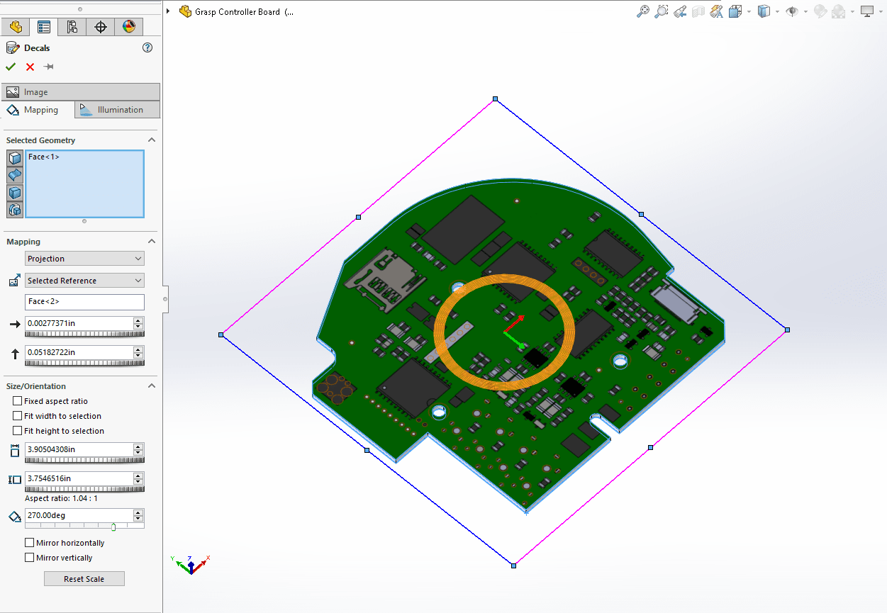
Step 6: Use the mapping controls on the Mapping tab to align, flip, and scale your image to your part. You should be able to line up the major features such as mounting holes closely. It may be necessary to turn off the Fixed Aspect Ratio option to control the stretch in one direction and not the other.
Step 7: Do a delete bodies on our surface bodies folder to remove the unwanted surface geometry.
Step 8: Exit and save the file.
Additional steps that can be added to the circuit board:
- You can apply a color to the board extrusion. Many boards are green in color.
- You can model larger connectors that you are interested in using or needing specifically in your design.
- You can model any of the larger components that will impact height clearances in your design.
- You can save the decal internal to the part file (Tools, Options, Document Properties, Model Display, Store appearance, decal, and scene data in model file)
The key take away is that decals are our friends. They are very lightweight when it comes to performance impact. By using this approach, we can assure we are working with clean solid body extrusions. Unhealed surfaces cause the software to both faces of the surface for all surface bodies, as opposed to just the exterior faces of a solid body. It will also help us keep the number of components to a minimum. In an assembly, SOLIDWORKS will calculate multi-body parts similar to assemblies, so even though a circuit board file may only be one part file, they are often made up of hundreds or thousands of bodies.
I hope the next time you work with a circuit board file that you will take the extra time to clean up your file. This simple process will allow you to keep the visual appearance of the circuit board in our model and provides you a significant boost in assembly performance.
Bryan Pawlak
Sr. Support Product Specialist
Computer Aided Technology, LLC