SOLIDWORKS Flow Simulation: Calculation of Hydrostatic Pressure
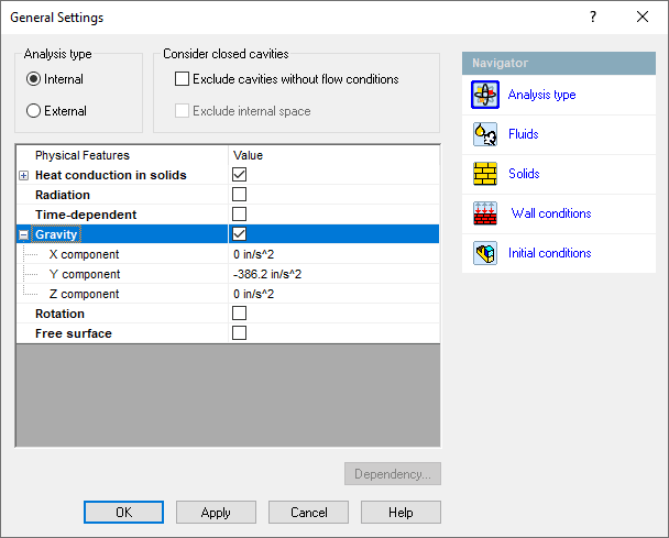
If you are an experienced SOLIDWORKS Flow Simulation user, chances are you’ve turned on the “Gravity” setting to account for buoyancy effects that exist when a fluid’s density changes with temperature. This is a very commonly used feature of the program.
Buoyancy is an amazing physics principle that allowed the Montgolfier brothers to make the historic first “lighter than air” flight in Paris in 1783.

One thing you may not be aware of is that when the gravity feature is activated, SOLIDWORKS Flow Simulation also turns on a setting called “Pressure Potential” in the Initial Conditions section.
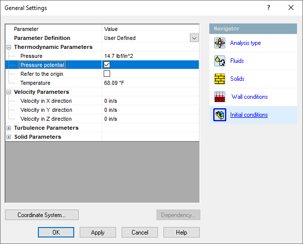
This additional setting is important because it accounts for the spatial variation of pressure according to the depth from a specific reference point, i.e., the increase in pressure from the weight of the fluid. For air, this variation is large only when dealing with significant distances. The air pressure at sea level, the “standard atmospheric pressure”, is about 14.7 psi (101 kPa). If we move to a higher elevation, e.g., when climbing a mountain or flying in an airplane, the pressure around us decreases significantly. Thus, the need for supplemental oxygen when attempting to summit a very high peak and for pressurization of commercial aircraft that fly above 10,000 feet or so.
For liquids, which have a higher density – water is about 800 times denser than air, the pressure variation can be significant, even with much smaller changes in elevation or depth. Think of the pressure on your ears when swimming below the surface – you don’t have to go very deep to feel the increased pressure. This is where SOLIDWORKS Flow Simulation’s Pressure Potential setting becomes most important, as it will calculate the added pressure at depth according to the formula:
![]() Patm = atmospheric pressure, ρ = density of the fluid, g = gravitational constant, h = depth.
Patm = atmospheric pressure, ρ = density of the fluid, g = gravitational constant, h = depth.
What is important to understand about using the Pressure Potential is that, by default, it uses the Global Coordinate System’s origin as the reference point to establish the pressure specified in the Initial Conditions dialog. It calculates the hydrostatic pressure throughout the computational domain based on this reference point. When designing in SOLIDWORKS, we might not think about the implications of the origin’s position. Not to worry, as this reference point can and, in some cases, should be changed within the project setup.
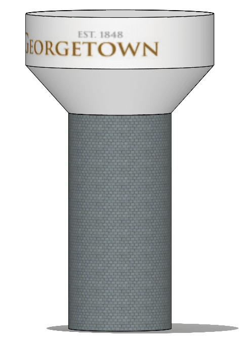
Let’s see how pressure is handled in a hydrostatic simulation of a municipal water storage tank like the one shown below. Elevated water tanks store treated water and help municipalities meet pressure and volume requirements at peak demand. Their reserves are replenished during off-peak hours by pumping water from a well or treatment plant into the tank.

I’ve made a simplified storage tank in SOLIDWORKS modeled after the one shown in the image, which is located in Georgetown, Texas. It is approximately 150 ft (45.72 m) tall and holds 2 million gallons (7,571 m^3) of water.
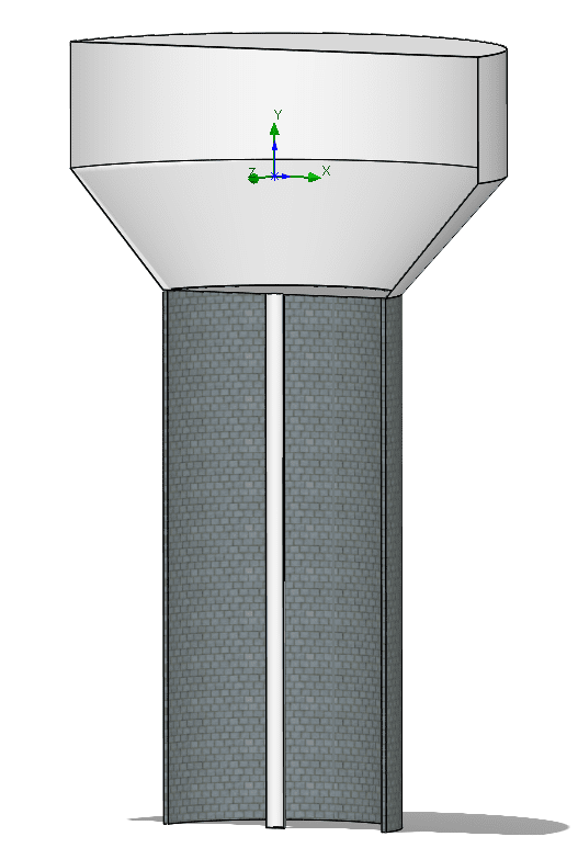
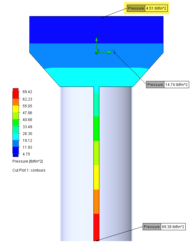
Make note of the location of the global coordinate system triad in the section view above. This is the default reference point and its location will determine the distribution of pressure, as you’ll see below. I’ve set up the first project with gravity in the negative Y-direction and assume that the tank is completely full of water. There are no flow conditions applied; I only want to calculate the static pressure distribution. Probing a cut plot of the pressure shows that the standard pressure of 14.7 psi (101 kPa) exists at the middle of the tank, since this is the location of the global origin. The pressure decreases above this point to 4.51 psi (31 kPa) at the top of the tank, which is unrealistic.
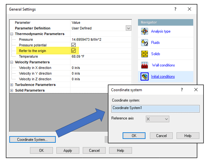
To correct this error, we can make use of the “Refer to Origin” setting within the Initial Conditions window. This allows us to select a user-defined coordinate system located at the top of the tank, which is the correct location of the reference pressure. I’ve done so in a project cloned from the first one and the correct pressure result is presented below.
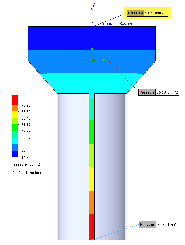
The calculated pressure at the bottom of the tank is 80.2 psi (553 kPa). A hand calculation check for the 150-ft (45.72-m) depth of water confirms that this is the expected pressure.
![]() P = 101,325 + 1000*9.81*45.72 = 550 kPa (79.8 psi)
P = 101,325 + 1000*9.81*45.72 = 550 kPa (79.8 psi)
If your project involves a device that is under significant pressure due to depth and it isn’t practical to represent the total amount of fluid that is above it in the project, e.g., a subsea device, you can use a reference coordinate system that is located at a point of known pressure and input that pressure in the Initial Conditions window. Using numbers from my example above, if the device of interest is under 150 ft (45.72 m) of water, I can simply use a coordinate system located at the device and set the pressure in the Initial Conditions to 80.2 psi (553 kPa)
The effect of pressure at depth is important when working with heavy fluids like water. So, when you set up your next project that involves fluid flowing from a tank or enclosure, or an underwater device, keep in mind how SOLIDWORKS Flow Simulation handles the calculation so you can get the most accurate results possible. I hope this informational blog has increased your understanding of the Pressure Potential and the origin reference used in the calculation and allows you to get even better results from your simulation efforts.
Kurt Kurtin, CSWE-Simulation
Technical Manager, Simulation Products
Computer Aided Technology, LLC