SOLIDWORKS Simulation Setup Tips – A Few Favorites
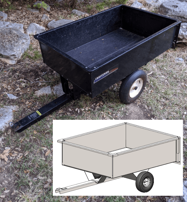
Everybody loves shortcuts, right? Who doesn’t like to save time and energy? Setup of SOLIDWORKS Simulation studies is no exception, so I’ll show some of my favorite time saving tips in the analysis of my small garden cart. You may notice that most of these tips are really just SOLIDWORKS CAD functions applied to Simulation, which shows just how well Simulation is integrated into the SOLIDWORKS interface!
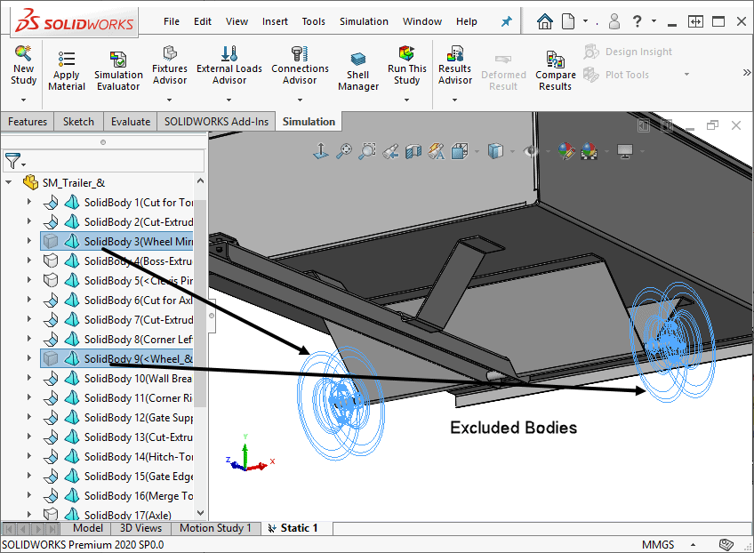
Hide Excluded Bodies:
Simulation has its own set of options. Open the Options window from the Simulation pull down menu, where you’ll find a convenient setting related to automatically hiding bodies that you exclude from the analysis. This setting allows you to focus only on those bodies that are included in the analysis.
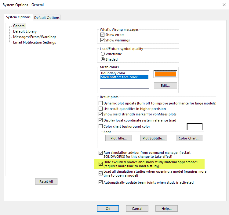
(Note that this option also toggles the appearance of bodies to what is set in the material properties data. Upon assigning materials, you’ll notice a visual change in the graphics area if the material appearance differs from that of the body.)
Quick Hide/Show:
For a quick way to hide/show bodies while viewing the model, use the tab/shift-tab key. It’s as easy as it sounds. Just hover over a component or body you’d like to hide and touch the tab key; shift-tab will bring it back. Pretty simple and useful, especially when viewing results!
Select Hidden Faces:
Another feature that has been around for a long time is “select other”, which makes it super easy to select faces or edges hidden beneath others. In the example below, I use this functionality to quickly apply a “no penetration” contact set between the face of the axle and its support tube.
Tangency Selection:
If I need to select multiple faces for a boundary condition, a quick way to do so is the use of “select tangency” from the right-click menu. The 38 highlighted faces shown below were selected with only six mouse clicks. Bonus tip: If you anticipate needing these faces for other operations, right-click on one and select “save selection set”. The set will be available later under the Selection Sets folder in the SOLIDWORKS feature manager tree.
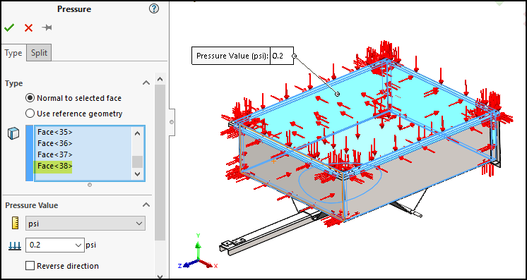
This pressure load, which might represent a full load of mulch isn’t needed; I know the cart can handle such a wimpy distributed load! For my analysis I want to consider a concentrated overload condition involving several very large rocks weighing a total of say 175 lbs. Not that I would ever push the limits of my cart, mind you, this is strictly a hypothetical example of what my neighbor might do when using my cart!
Split Lines:
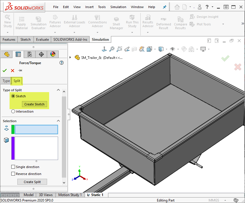
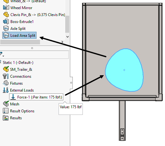
To simulate the load placement for the overload condition, I need to concentrate a force on a small area of the cart floor where the rocks will sit. Split lines are a perfect way to do this and can be set up on-the-fly during the load application. So, I’ll start my force boundary condition, switch to the “Split” tab at the top of the property manager and use the “Sketch” type of split as follows:
- pick the “Create Sketch” button to start the process,
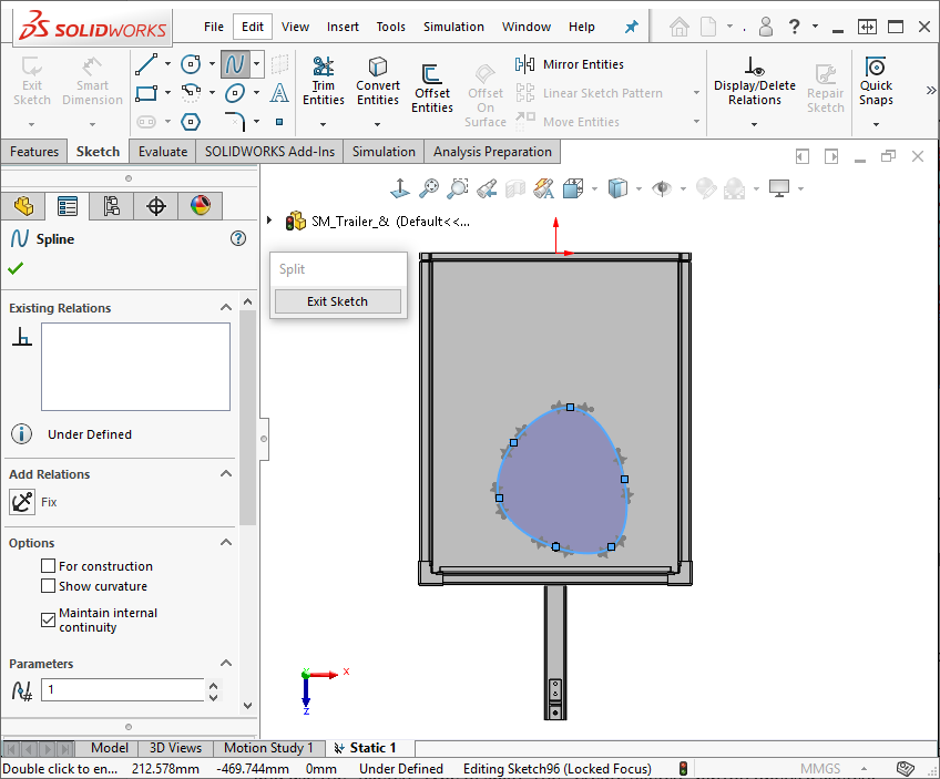
- pick the floor face to locate the sketch,
- draw the perimeter of the desired load application area using the spline tool,
- exit the sketch to complete the creation of the split on the floor of the cart.
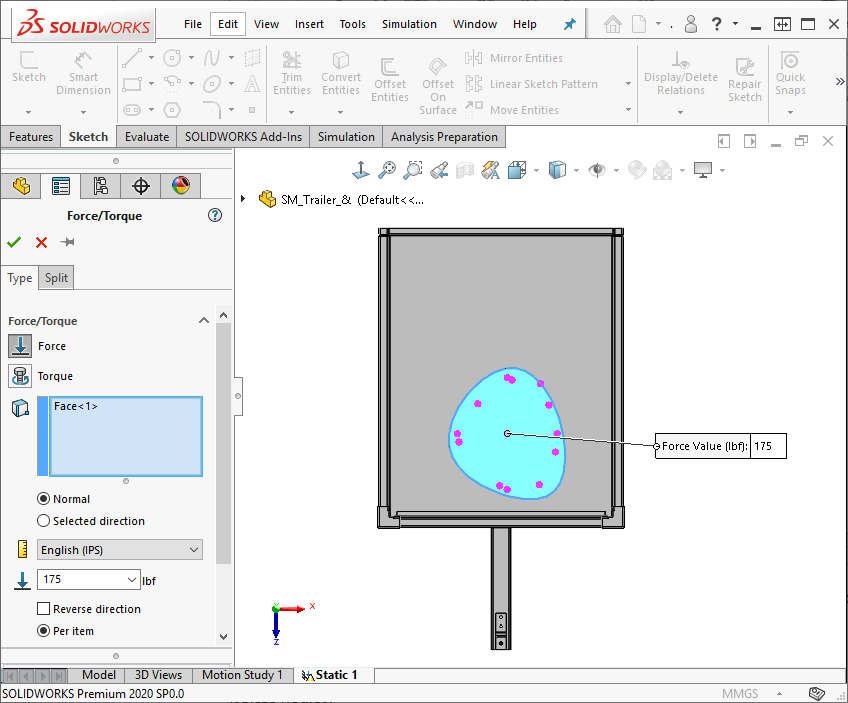
I can then apply the weight of the stack of rocks, 175 lbs, to the newly-defined face. Notice that the result of doing this is a new split line feature in the tree. I’ve renamed it appropriately after completing the force boundary condition.
The cart was modeled using the sheet metal functionality within the CAD environment; therefore, SOLIDWORKS Simulation will automatically mesh and bond the areas of contact between the sheet metal bodies by finding the mid surface of each and creating an efficient shell mesh. All that remains in the setup is the addition of a few bonded contact sets in areas where solid and shell meshes interact, applying the proper fixtures, and assigning steel material to all the bodies.
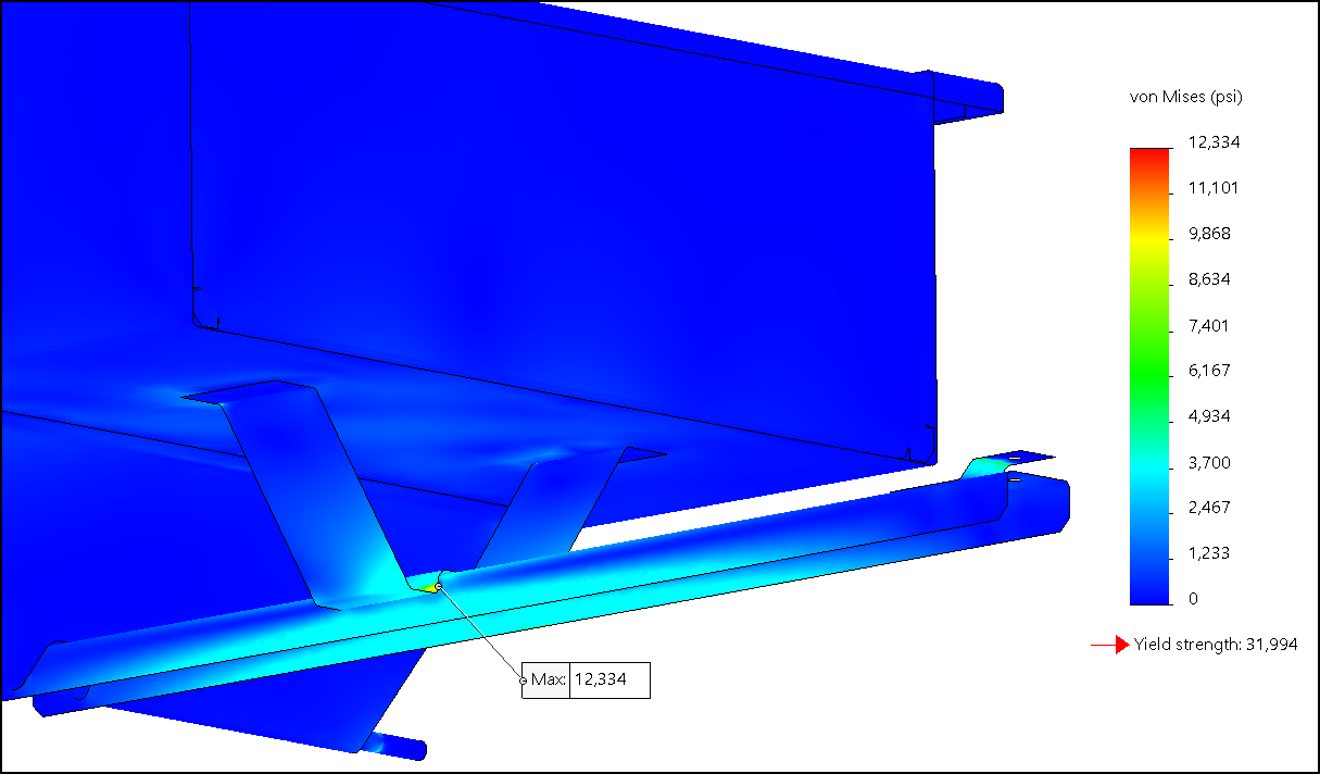
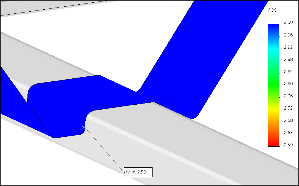
After meshing and running the simulation we can see the outcome, specifically, if my cart will hold up to my, excuse me, my neighbor’s 175 lb overload condition! As it turns out, all is well, and I can tell my neighbor he can borrow the cart because the deflection is very low and the 32 ksi yield strength of the steel won’t be exceeded. In fact, the minimum factor of safety (FOS) based on yield strength is 2.6, as seen in the plot below. Bonus tip:: You’ll notice that this result plot has been customized to apply the FOS result only to the most highly stressed body. This was done in the Advanced section of the FOS plot property manager during plot creation or subsequent edits.
From garden carts to semi-trailers, these SOLIDWORKS Simulation tips should help you save time and effort in your analyses, especially when it comes to checking out what your neighbor might do to your stuff before you loan it to them! Don’t forget to apply these tips the next time you use SOLIDWORKS Simulation. Now, I gotta go move some, err, I mean my neighbor needs to move some rocks…
Kurt Kurtin
Technical Manager – Simulation Products
Computer Aided Technology, LLC