Design Intent: Part 1
Part I
I am working with a client who sees the power and value from SOLIDWORKS over AutoCAD Inventor. How to deal with legacy data is always a massive pain point for customers, however. They soon will no longer be able to access data that is still in the native Inventor file format (.iam, .ipt) that their previous CAD software utilized and must find other methods of retaining their intellectual property.
Where possible, I suggest converting the files into Parasolid files (.x_t, .x_b) or STEP files (.stp). Parasolid files are the useful to convert into SOLIDWORKS because Parasolid is the kernel from which SOLIDWORKS is built. I also had strong success with STEP files. The main difference between the two is that STEP files retain the original part name, and for that reason may outweigh the benefits that Parasolid can provide.
However, neutral file types like these give you no control over what information you wish to relay in the model or drawings and no access to modifying features, patterns, or sketches. This is where the engineering designer must get smart. The engineer must consider design intent. How should the drawing look? What do they wish to control? How should the model behave after modifications? Will they need to generate a cut list of components? Will this be outsourced for manufacturing, or done in-house? All of these — and more — should be considered after converting your AutoCAD files into Parasolid or STEP files.
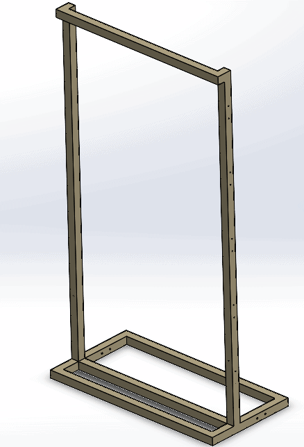
Figure 1: Basic Frame Structure
If you’re outsourcing a component for manufacturing and no changes need to be made, leaving it in the STEP file format is fine. The required measurements can still be extracted and utilized in your or your manufacturer’s native CAD software and is the most widely accepted neutral file format.
It’s not often that design changes don’t need to be made, especially if your Company’s niche is providing custom components and assemblies. Plus, the ability to make changes on the fly quickly is why CAD is such a powerful tool. This is where a simple solid body representation isn’t enough.
Let’s look at this basic frame structure (Figure 1) that has been converted into a Parasolid. I chose this frame to work with first because the entire frame can drive the whole assembly. Any changes that I might make dimensionally, I would want it to be here.
Before translating the frame into usable features, it’s important to see what sort of information we already get from a step file. We can do things such as create drawings, add measurements, add hole diameters, and detail sketches. The details lack some polish, as you can see in Figure 2.
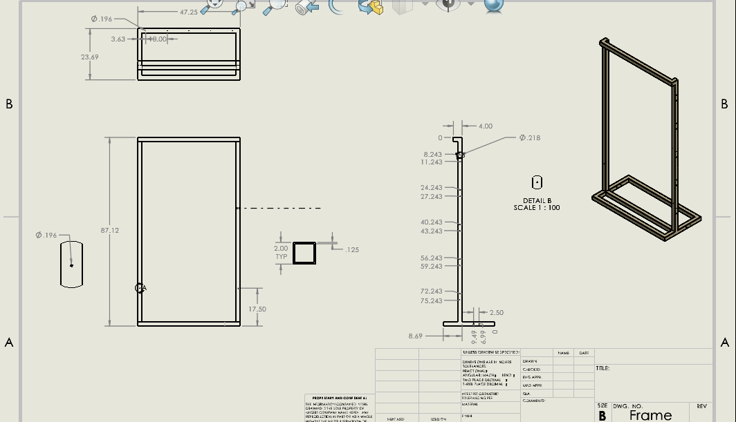
Figure 2: Drawing of a .STP file
It is somewhat understandable, but it’s not clear how the components of the frame are welded, the lengths of the components, or the angles of some of the cuts. The drawing is likely missing key dimensions that could make this drawing under-defined, leaving ambiguity and room for error. You’ll also notice that this is all one solid body, which isn’t realistic for this method of manufacture.
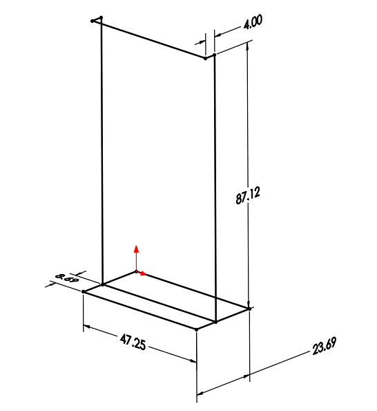
Figure 3: 3-D Line Sketch of Frame
With SOLIDWORKS Weldments, you can create a “Weldment Cut List” from a sketch that creates separate bodies when an additional piece of part stock is necessary. SOLIDWORKS then details the lengths and stock types required for the construction of this component, which works similarly to a BOM. You can also create separate sheets that detail hole callouts and Hole Wizard locations. Let’s assume this is being made in-house, and therefore we want to make sure we have clear assembly instruction for the individuals in the shop.
I start by opening the Parasolid (or STEP) file in SOLIDWORKS. This is so I can extract all the necessary measurements using the “Measure” tool to create my sketch. I grab my 3D sketch tool and begin a sketch on the Top (ZX) plane, sketching a general outline before adding my relations. In this case, I am going to make sure my lines in the sketch are all restrained to Along X/Y/Z, because all lines in the sketch are either parallel or perpendicular. Then, I add dimensions (Figure 3). When I add all of my relations first, any time I make modifications in the rebuild, I won’t get any sketch distortion.
Now that the wireframe is done, I can utilize SOLIDWORKS Weldments to create “Structural Members”. I can select specific stock types, groups, and profile locations here to build out the frame completely.
The amount of information that can now be extracted is much more powerful than the previous step file. I now can add a “Weldment Cut List” that calculates the lengths of all the weldment bodies I have added. I can also add balloons to each item in the main drawing that indicate where the bodies are located. Then, I will reference these bodies individually in additional sheets to provide clarity on how to cut specific pieces and where to place the holes.
The results are shown in Figure 4-7.
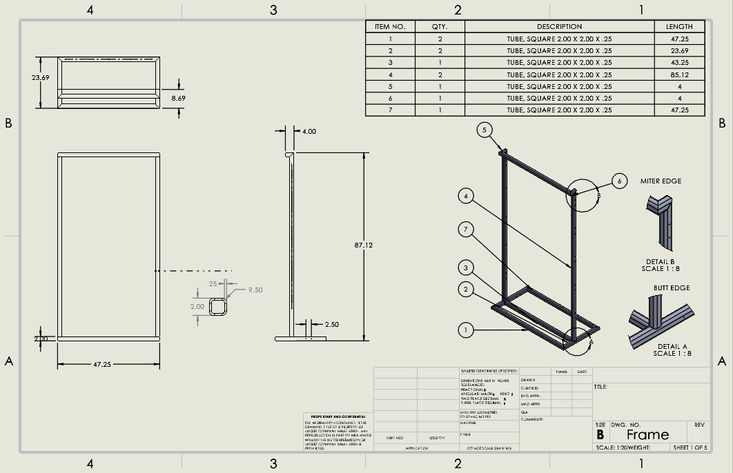
Figure 4: Main drawing page includes a detailed cut list with balloons and detail views on weld types.
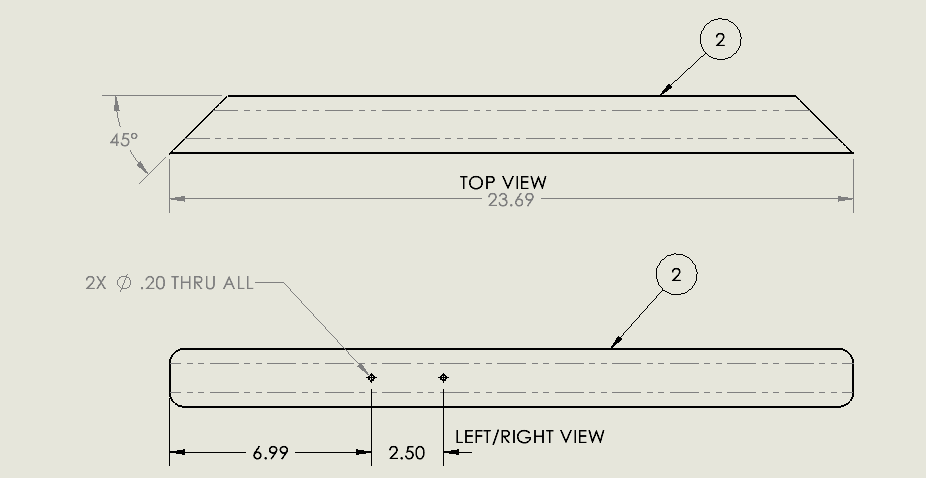
Figure 5: Item 2 from cut list have angled edges and better hole callouts
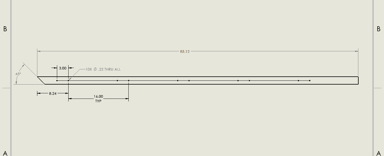
Figure 6: Item 4 from cut list details angled cut and hole placements clearer than the parasolid drawing
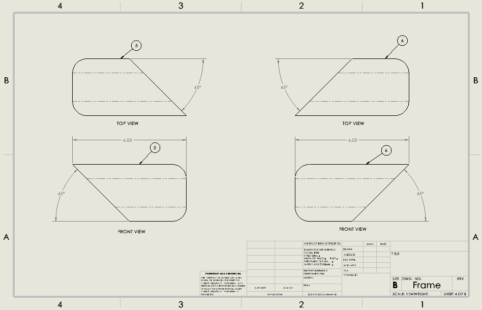
Figure 7: Item 2 from cut list has 45 degree angles on a both the FRONT view and TOP view and are unique to one another.
This concludes part one of a two-part series. Later we will undertake using SOLIDWORKS Feature Recognition for both standard and sheet metal parts.
I hope this helps you in making decisions for future modeling and converting files. Making smart engineering decisions to boost your productivity in the future is incredibly important and should never be overlooked.
Thank you for taking the time to read this post and I hope it proves useful to you.
Jordan Kleinschmidt
Application Engineer, CSWP
Computer Aided Technology, LLC