SOLIDWORKS Flow Simulation: A Tesla Cybertruck Case Study (Part 2)
In part 1 of this Blog article I investigated the drag characteristics of the Tesla Cybertruck and explored how symmetry boundary conditions can be used to speed up a flow analysis project in SOLIDWORKS Flow Simulation. In part 2, I am going to demonstrate some of the nuances for correctly setting up a “Virtual Wind Tunnel” in SOLIDWORKS Flow Simulation.
Before the widespread adoption of Computational Fluid Dynamics (CFD), engineers who sought to explore the aerodynamics of different vehicle shapes would typically book testing time at a wind tunnel facility. They would build scale models of candidate shapes and measure the drag of these candidates in the wind tunnel. This is a very costly exercise; wind tunnel time is very expensive, as are the costs associated with constructing the scale models and hiring technicians to run the tests and crunch the numbers. Fortunately, CFD has largely replaced this expensive process, but care is required to ensure accurate replication of the physics of vehicle flow. Luckily, SOLIDWORKS Flow Simulation makes the set-up easy.
In real life, a vehicle moves down a road and creates drag. There is relative motion between the vehicle and the road and between the vehicle and the air, but (assuming a windless day) there is no relative motion between the air and the road. In flow vernacular, there is no boundary layer at the interface of the air and the road.
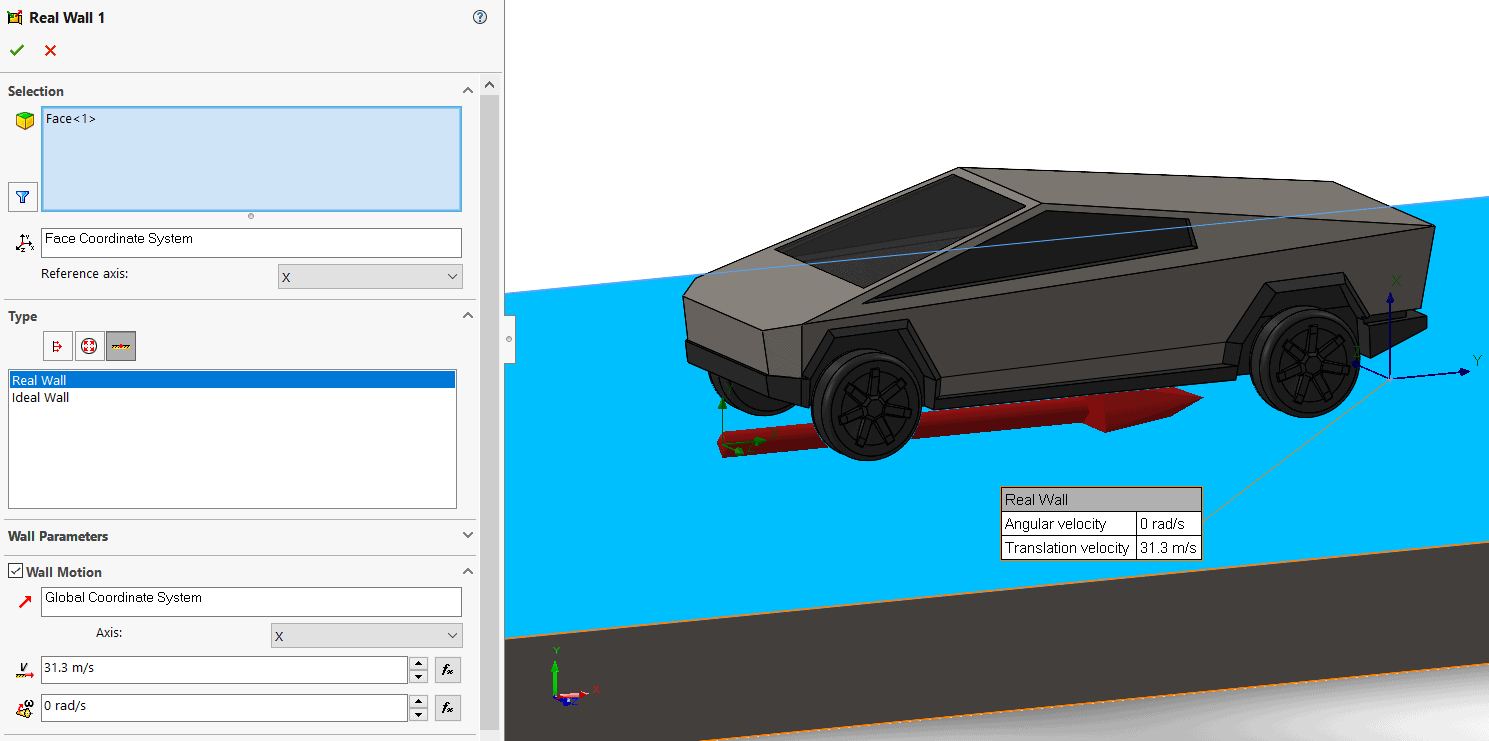
In a typical external flow simulation project, we will fix the vehicle in place and then move the air relative to the vehicle using an inlet velocity boundary condition. This creates the correct relative motion and boundary layer between air and vehicle. However, if we are not careful with our set-up, and we do nothing more, we will have created relative motion between the air and the ground. This will create an unwanted boundary layer at this interface which could potentially affect the results. Fortunately, SOLIDWORKS Flow Simulation provides an easy way to avoid this; all we must do is tell the software that our ground is moving at the same speed as the air. We do this by setting up a Real Wall Boundary condition, with Wall Motion, in the Boundary Condition property manager, as shown below. In our case the Tesla Cybertruck is moving at 70 mph (31.3 m/s), so our inlet velocity is 31.3 m/s and the road also needs to move at this speed in the same direction as the air flow.
That takes care of the interface between air and ground, but there is one other interface that we need to consider in order to replicate the physics. We need to consider what is happening to the wheels (and tires). In real life the wheels are turning and driving the vehicle forward, creating a local rotating flow near the wheels. So, we need to correctly simulate this relative motion between the wheels, the vehicle body and the air in our Virtual Wind Tunnel. There are 2 ways we can do this in SOLIDWORKS Flow Simulation.
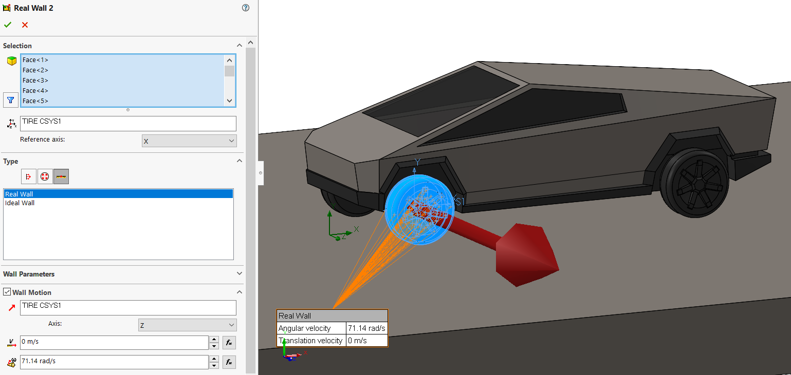
The first method is to use a Real Wall Boundary condition, with Wall Motion, on the wheels. This is similar to the Real Wall Boundary Condition from above, but instead of specifying a linear velocity, we specify an angular velocity. First, we must calculate the angular velocity (or RPM) of the wheels when the vehicle is moving at 70 mph. In the case of the Tesla Cybertruck, this is 71.14 radians/sec. We also need to create a local coordinate system centered on each of the wheels to specify the axis about which each wheel is rotating. We need to select all the faces attached to the axle of the vehicle.
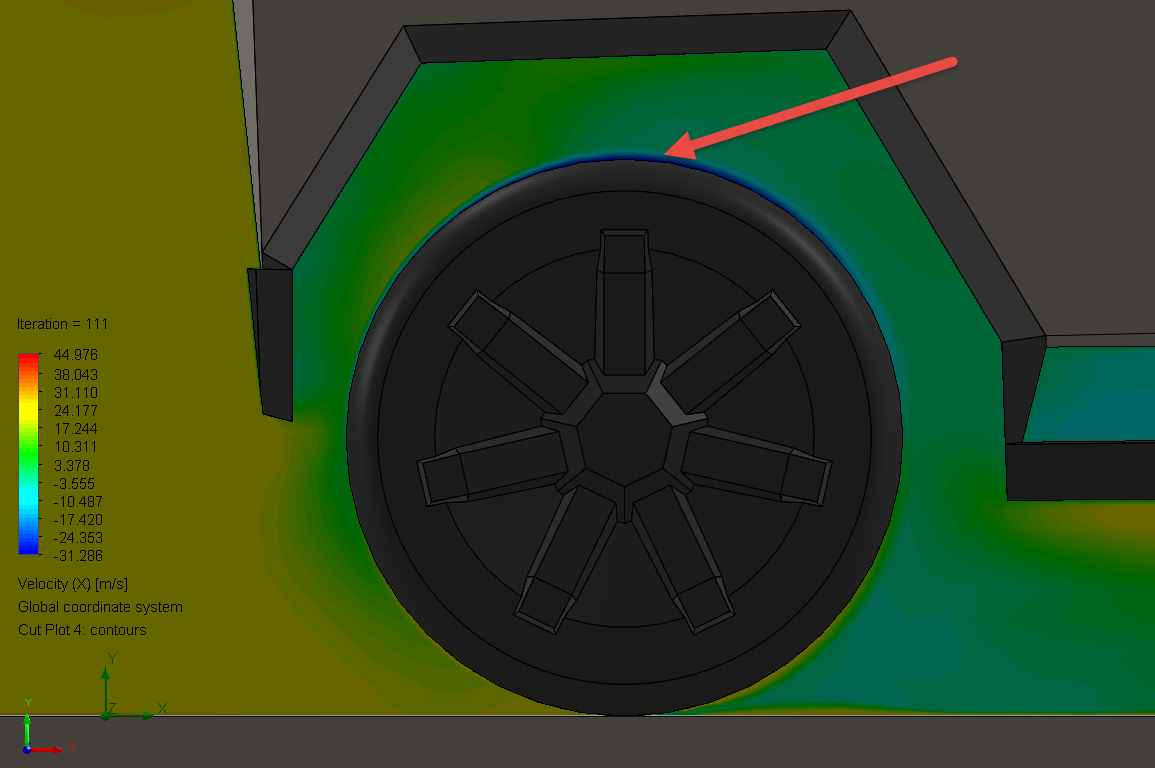
As a result of the no-slip condition, air attached to the tires and wheels will now rotate at 71.14 rad/sec, which in the case of the air on the top hemisphere of the tire is opposite to the direction of global air flow! We can study this affect with a cut plot showing X component of velocity through the center of the wheel. The red arrow is pointing to the area of the tire that has a negative X component of velocity.
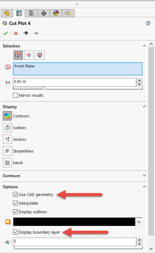
To highlight this very local flow phenomenon in proximity to the tire boundary layer, we must activate both the ‘Use CAD geometry’ and the ‘Show Boundary Layer’ button on the Cut Plot property manager.
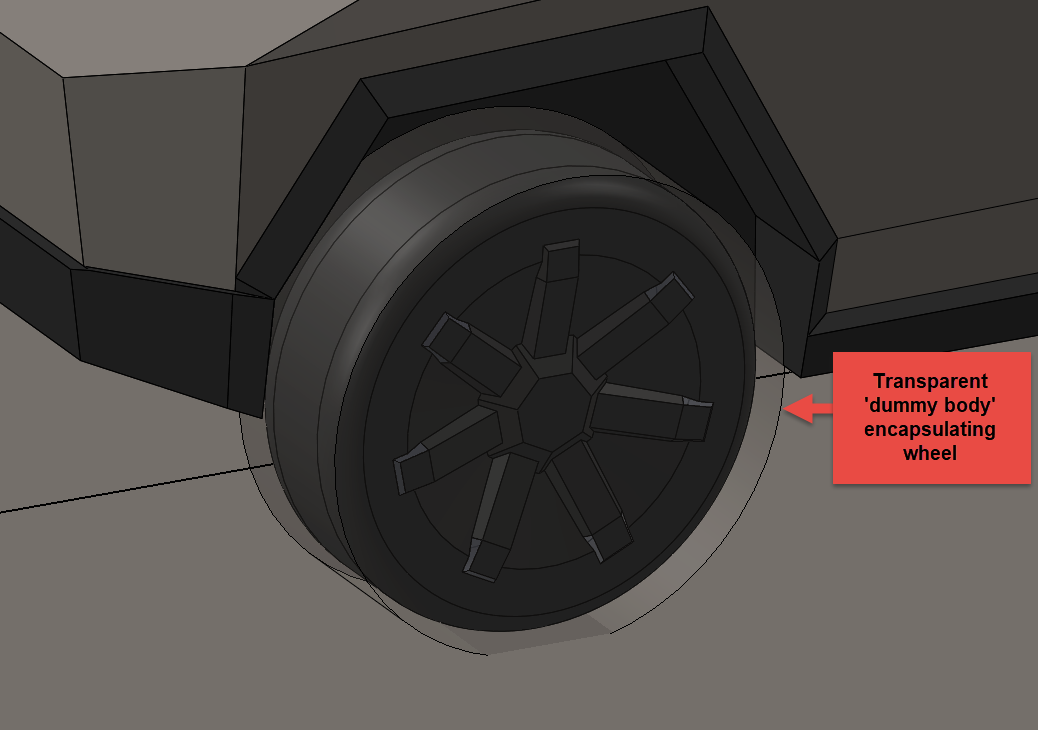
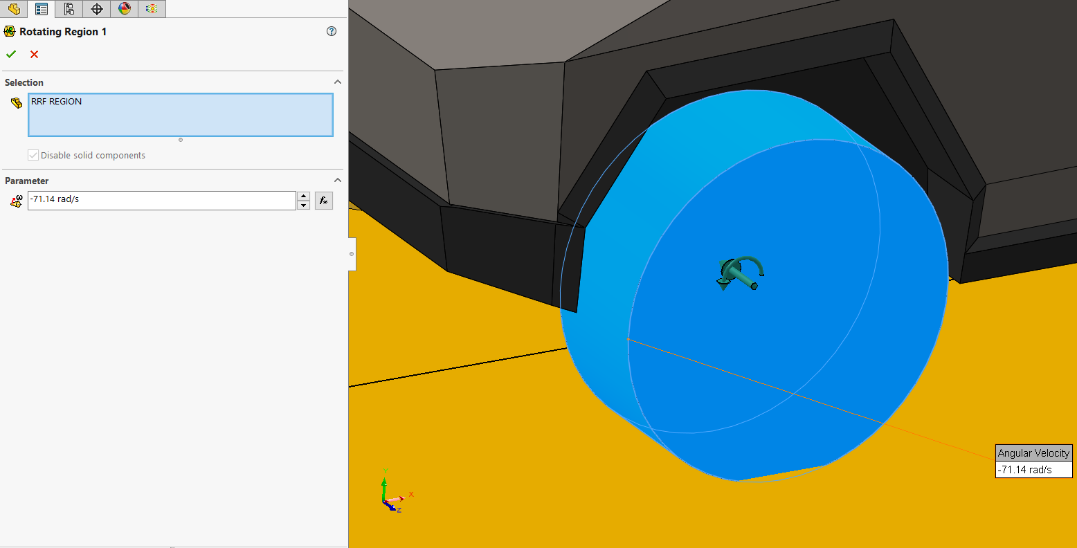
The other method we can use to simulate the flow effects of a rotating wheel is to use a sliding mesh rotating region in SOLIDWORKS Flow Simulation. A detailed discussion about rotating regions is beyond the scope of this Blog, but there is a good article on the subject here. In our case setting up a rotating region is relatively easy. In our CAD model we simply create a disc shaped ‘dummy body’ that fully encapsulates the wheels and tires. We then select this as our rotating region, give it the same angular velocity (71.14 radians/sec) and make sure the ‘dummy body’ is disabled in component control.
So which method (moving wall or rotating region) should we use? The answer, as is often the case in any simulation project, depends on the goal of your analysis. The rotating region approach best captures the physics, but it comes at the cost of a significant increase in computational time. The reason for this is that simulations that use sliding mesh rotating regions are time dependent (transient). Transient analyses take significantly longer to solve. On the other hand, the moving wall method can be solved as a steady state problem. The issue with this approach is that in order to resolve the high velocity gradients near the wheels, we need a much finer mesh in these areas which also increases solution time.
What if we just ignored the fact that the wheels are rotating, and the ground is moving and ran the analysis anyway. Is this a valid approach? Certainly, we aren’t capturing the physics correctly, and therefore we have sacrificed some accuracy. However, if the goal of our analysis is to quickly assess the aerodynamic characteristics of some candidate body shapes, and rank them according to their drag, then ignoring the local flow phenomena near the wheels and ground is probably OK. It’s unlikely that the ranking of potential body shapes will change whether or not we are accurately capturing the local flow physics near the wheels, so this could be a good way to shorten the candidate list.
To better understand the trade-offs between greater accuracy and increased run time, I ran the Tesla Cybertruck four different ways and tracked drag, mesh size and CPU time. I ran the rotating region study for 1 second of physical time. At 70 mph the Tesla Cybertruck will travel 31.3 m, which is 5.3 lengths of a Tesla car. In all cases I took advantage of symmetry. The results are shown below.
As you can see, the rotating region approach is very expensive computationally. The moving wall approach adds a significant number of cells near the wheels and wheel wells, but still runs relatively quickly on a good workstation computer. Without any moving wall or rotating region boundary conditions associated with the wheels, the run times are extremely short. Depending on the goals of your analysis any one of these approaches could be valid.
The one big advantage of the rotating region approach is that you can create some cool animations of the rotating flow to impress your manager! The video below shows a cut plot of velocity including streamlines on the center plane of the vehicle, overlaid on an animation of turbulent energy propagation.
I hope this Blog highlighted some important factors to consider when using SOLIDWORKS Flow Simulation to create a Virtual Wind Tunnel for external vehicle flow analyses. Now go design some innovative products with the help of the comprehensive analysis tools available in SOLIDWORKS Flow Simulation.
Alon Finkelstein
Simulation Product Specialist
Computer Aided Technology, LLC