SOLIDWORKS Visualize: Cutting Corners for More Realism
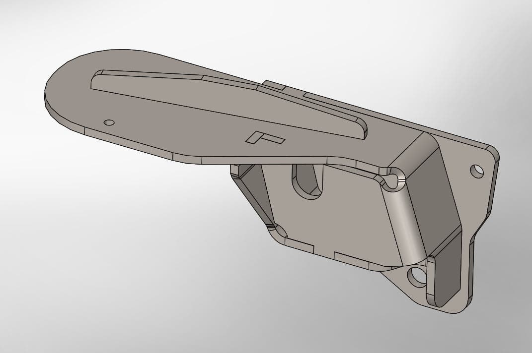
SOLIDWORKS Visualize is an amazing tool to bring realism to designs by enabling users to create realistic renderings to any CAD design. There is one fatal flaw…SOLIDWORKS Visualize will only render the design as realistic as you’ve created it. Confused? Let me clarify, let’s say you create a design in SOLIDWORKS that is perfect for your engineering needs like this.
And now you want to create an awesome rendering for your sales and marketing team, so you push that design to SOLIDWORKS Visualize, apply awesome materials and great lighting, but your rendering still looks not-so-real.

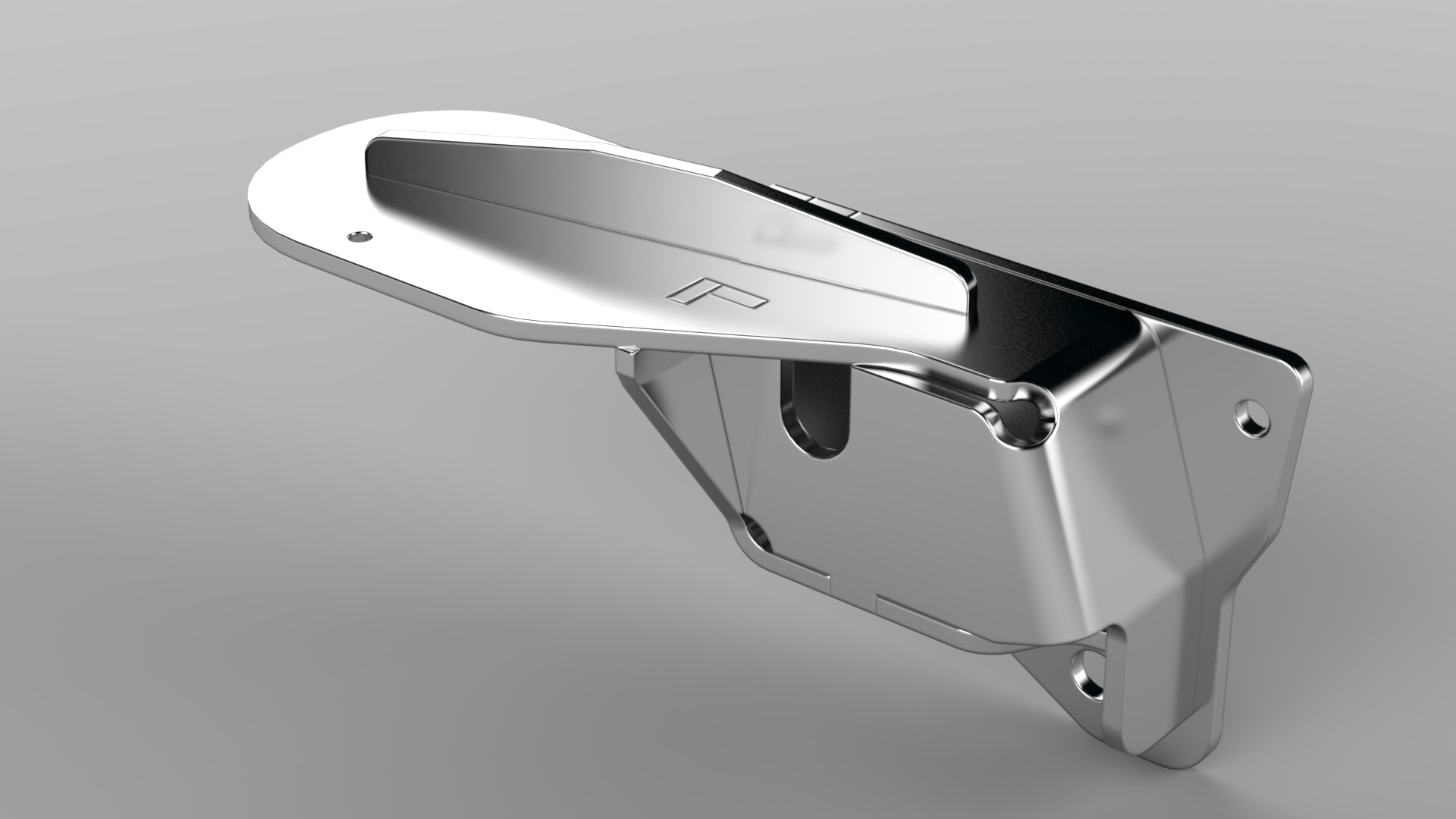
What you’re really after is an image that looks something closer to a true representation of what the part will truly look like.
So why do these two renderings look so different? It’s all about cutting corners! The first image is using the CAD data as it was provided from SOLIDWORKS which had all sharp edges. This is not realistic and will cause a sharp transition at the edges of the model and our eyes pick up on that fact very quickly. The second is using more realistic rounded edges like we would expect from a part like this. This type of rounding can be achieved a couple of ways.
One way to get there is by adding fillets to the SOLIDWORKS model. This technique is often used but can be frustrating and time consuming when you are trying to provide the image as quickly as possible to sales and marketing. SOLIDWORKS is a CAD tool which is great at creating engineering level detail so the fillets will need to be as geometrically accurate as possible.
The second and easier method is actually right inside of SOLIDWORKS Visualize. It is the method that was used to create the second rendering. You can use the ‘Corner Radius’ tool to add rounded edges uniformly over entire parts right from the geometry tab! Simply adjust the corner radius value until you dial in the desired edge rounding you think makes your part look more accurate to the finished version.
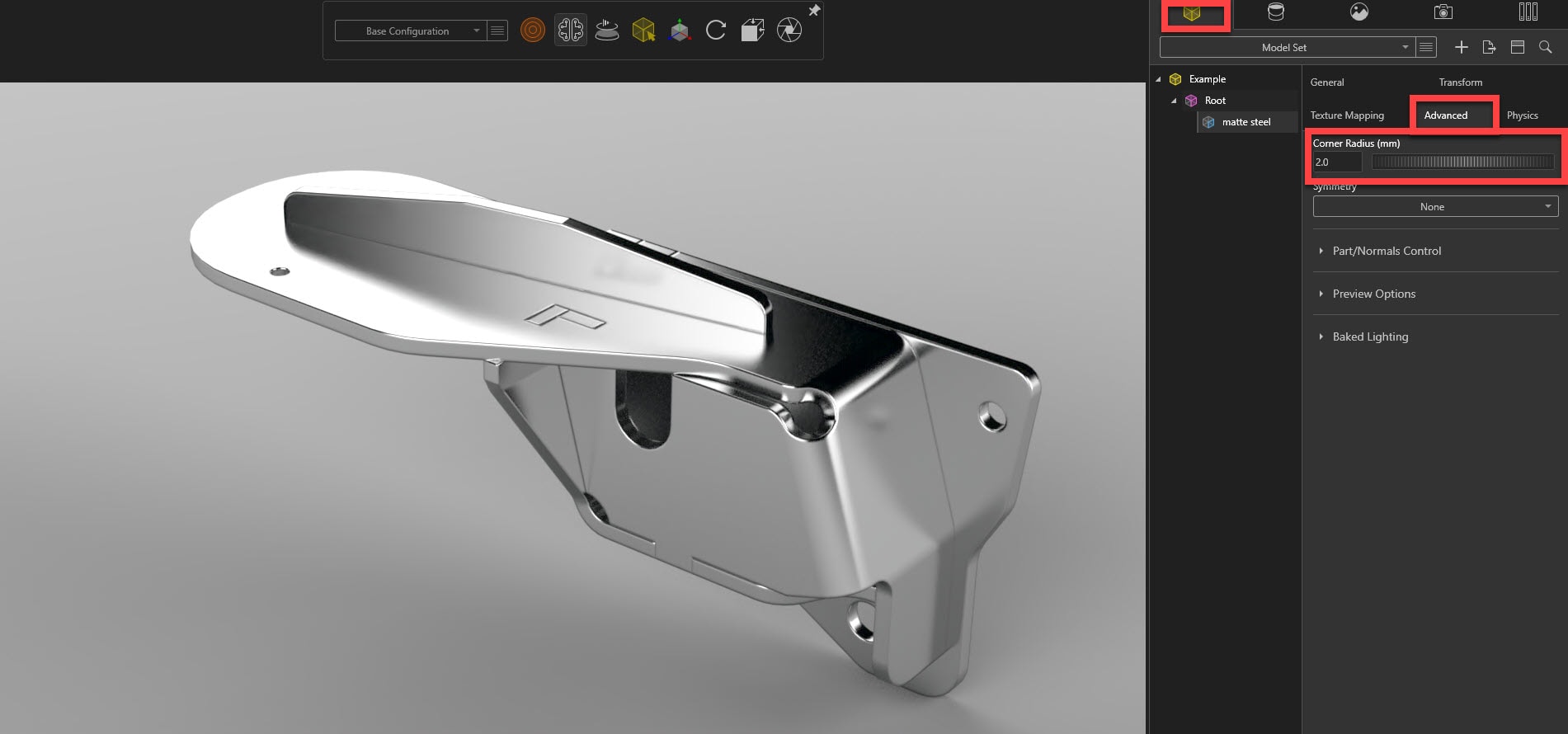
I’ve found adjusting this value by a factor of 10 (up or down) will help quickly dial in to the rough size and then you can make slight adjustments as necessary. So remember, the next time you have a CAD model with sharp edges, try using the ‘Corner Radius’ option to quickly and easily cut the corners and add more realism to your SOLIDWORKS Visualize rendering.
Brandon Nelms
Application Engineer – CSWE, Field Technical Services
Computer Aided Technology, LLC