Being Transparent with SOLIDWORKS
Have you ever been working in SOLIDWORKS and had a face go transparent with no idea how to get it back? How about an entire part? Occasionally, it may seem SOLIDWORKS has a mind of it’s own in terms of making elements transparent. This blog will go over all the ways that elements can become transparent within SOLIDWORKS and the best way to make these elements visible again.
Transparency within SOLIDWORKS can be a very powerful tool. Having the ability to selectively turn elements transparent and leave them in that state can be invaluable when designing complex geometry. Most transparency issues arise when a user accidentally turns an element transparent or has to bring back many transparent faces. To handle transparency issues most effectively it is important to understand what elements within SOLIDWORKS can become transparent.
The elements that can become transparent are Parts, Bodies, Features, and Faces. When dealing with the transparency of Parts/Bodies/Features they operate in a similar manner. Faces, however, are a unique case and will be discussed separately. Here’s how to manage each:
Parts/Bodies/Features
SOLIDWORKS describes parts, bodies and features as:
Part: A single 3D object made up of features. A part can become a component in an assembly, and it can be represented in 2D in a drawing.
Body: A solid body is a collection of one or more surfaces that are knit together to define a closed volume.
Feature: An individual shape that, combined with other features, makes up a part or assembly. Some features, such as bosses and cuts, originate as sketches. Other features, such as shells and fillets, modify a feature’s geometry. However, not all features have associated geometry. Features are always listed in the FeatureManager design tree.
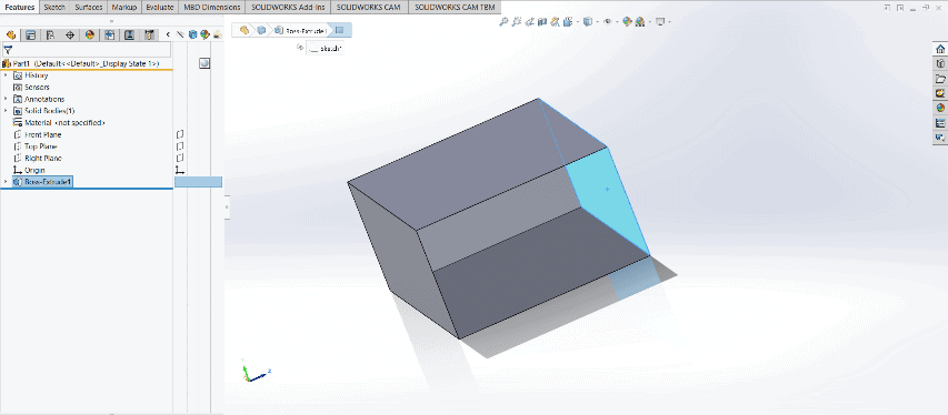
The first place to look when one of these components is transparent is in the display panel within the feature manager tree. This location is hidden by default and must be expanded.
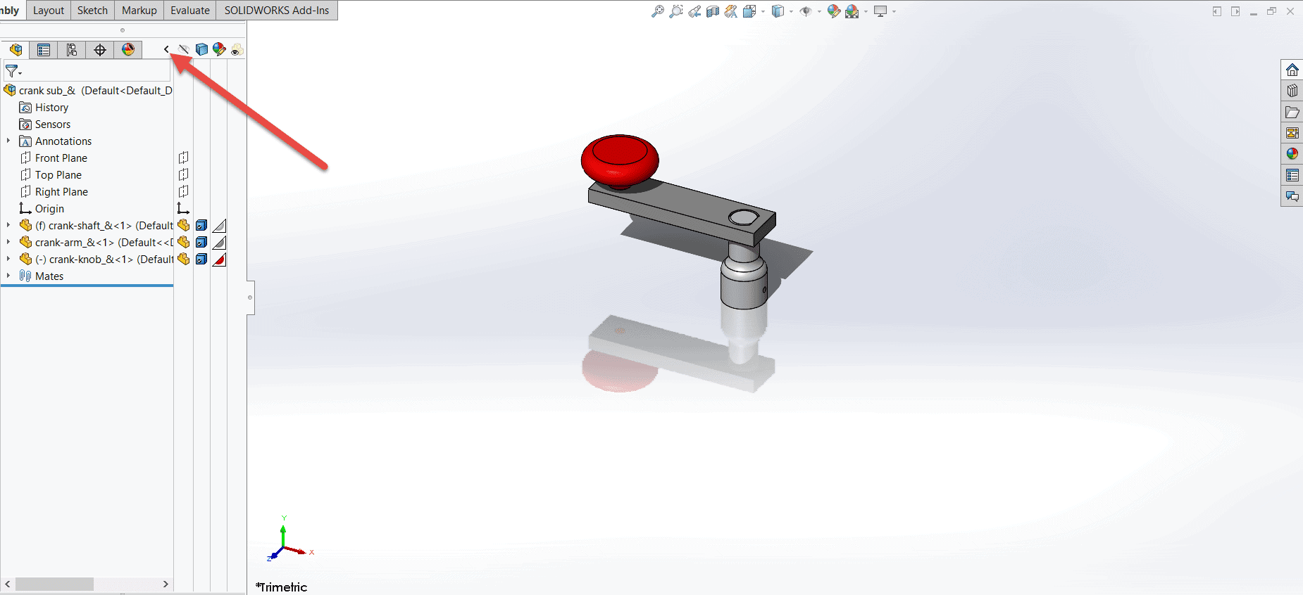
Once the display panel is visible the transparency can be toggled on and off for the parts, bodies, and features shown in the feature manager. Simply selecting the furthest right column will toggle the transparency.
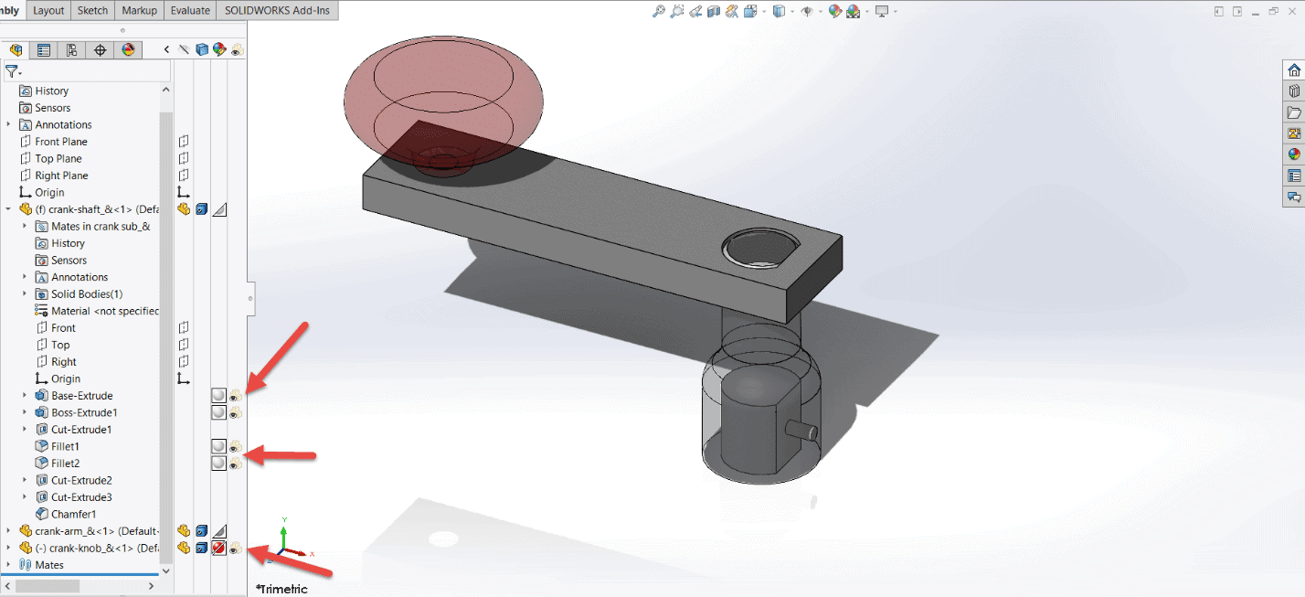
The above example shows how features and parts can both be turned transparent in the FeatureManager. When in the assembly space, the parts can also be graphically selected and have their transparency toggled. This does not include the features and solid bodies.
If something is still transparent after checking the Display Panel in the FeatureManager the most likely cause is a transparent face.
Faces
SOLIDWORKS describes a face as a selectable area (planar or otherwise) of a model or surface with boundaries that help define the shape of the model or surface. For example, a rectangular solid has six faces.
The major difference in transparent faces is that they do not show up in the FeatureManager. Applying and removing transparency to faces can only be done by graphically selecting them with a right click and then choosing “Change Transparency”.
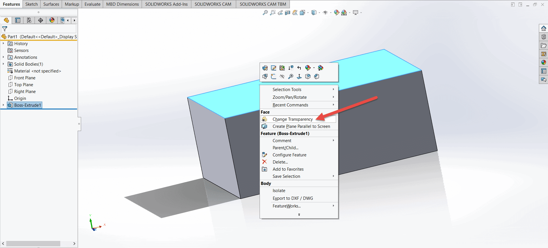
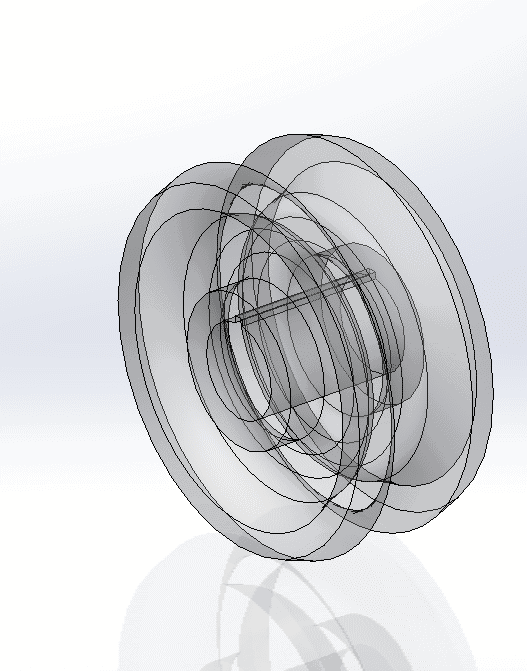
This is straight-forward when selecting a face to make transparent. Making a transparent face solid again is another matter. When there is nothing behind a transparent face SOLIDWORKS will default to selecting the transparent face.
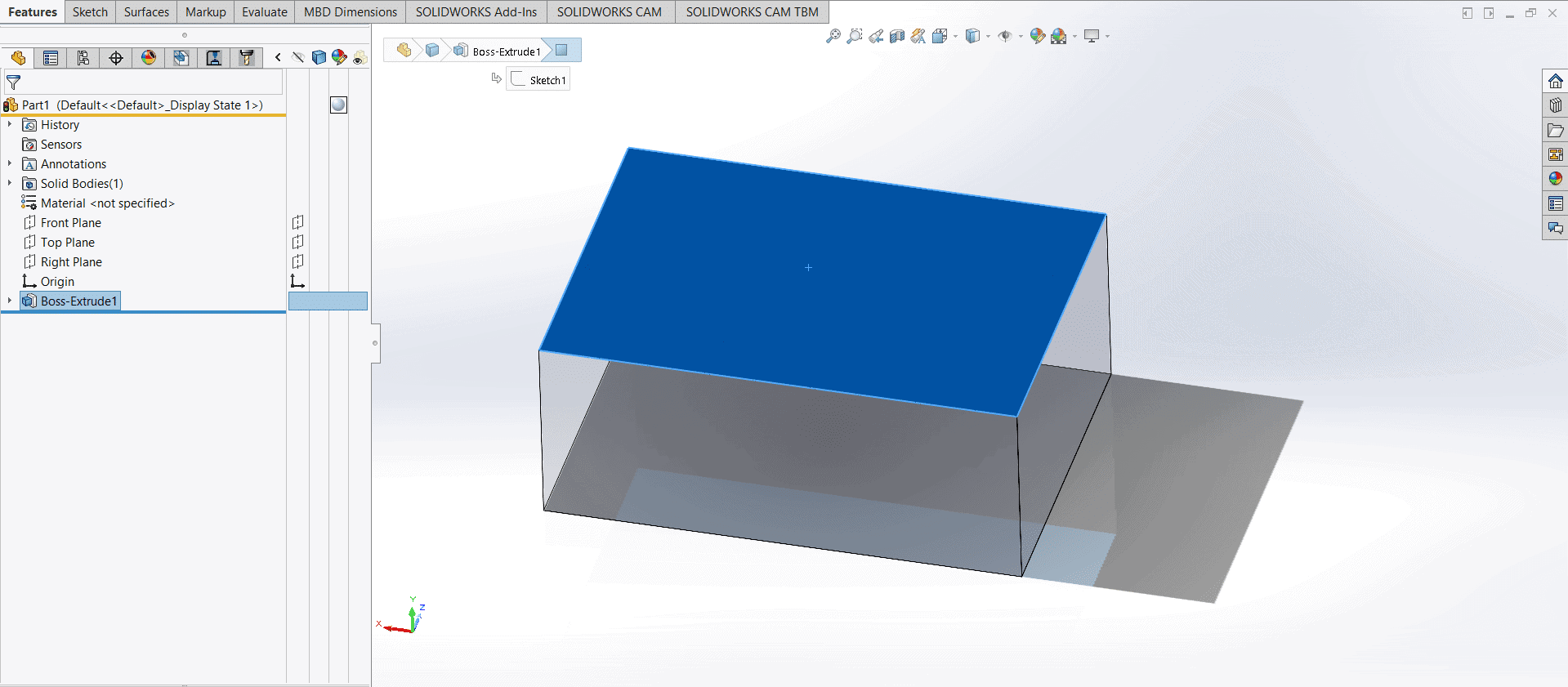
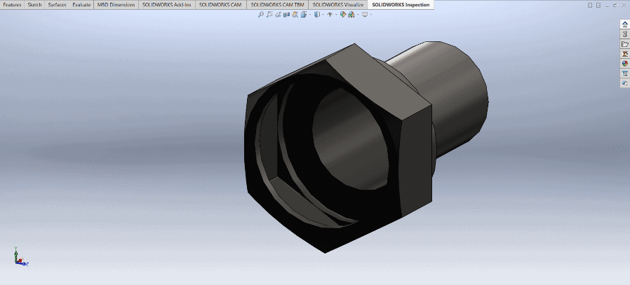
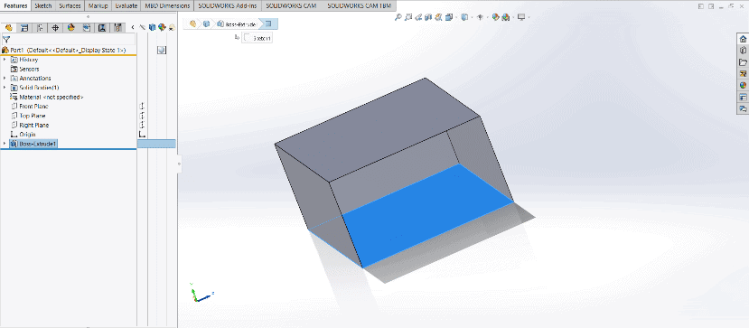
The example above shows a completely transparent block. Since there is nothing “solid” behind any of the transparent faces SOLIDWORKS will default to selecting the nearest transparent face. The example below shows a cube with all it’s faces solid except for one. In this scenario SOLIDWORKS will always default to selecting the solid faces behind the transparent one.
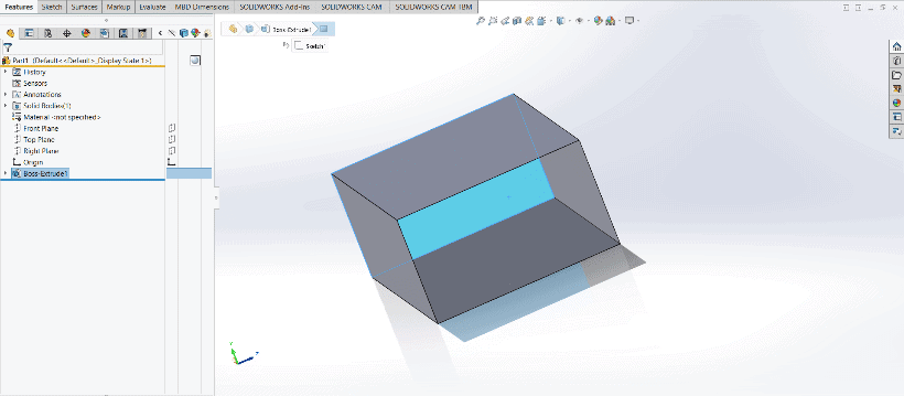
When it comes to selecting these transparent faces that have only solid faces behind them, there are a few options.
- The first and simplest option is to select the transparent face while holding the SHIFT key. This will allow the user to graphically select the transparent face and then right click it and change the transparency.
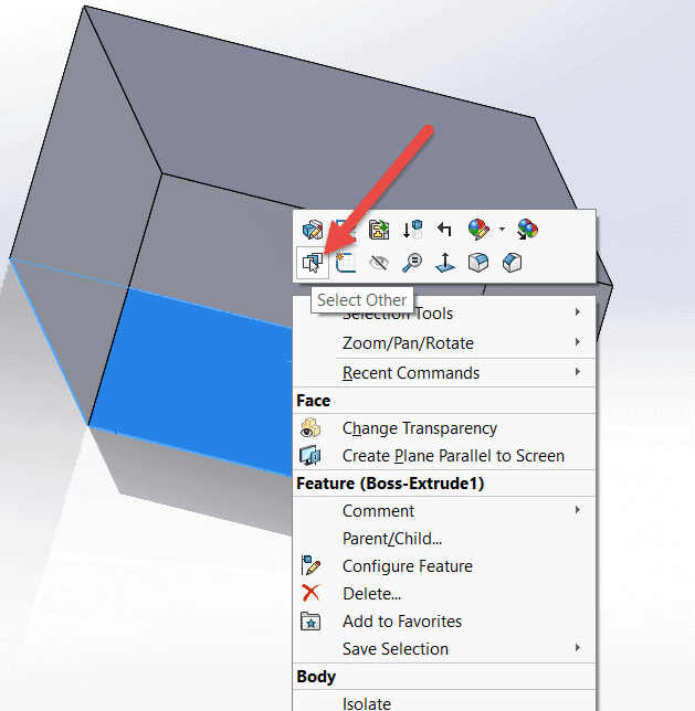
- Using the select other command. This can be used by right clicking the transparent face, which will select the solid face behind it, and then choosing the select other icon shown below. This will allow for the selection of any face that is behind or in front of the selected face.
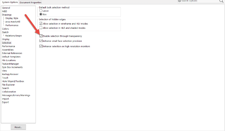
- The third options is to completely disable the ability to select through transparent faces. This option can be found in the system options under the selection tab.
The options above are particularly useful when trying to select a single face to make transparent again. If there are a larger amount of faces that have become transparent there is a much better method for toggling all the faces to become transparent again.
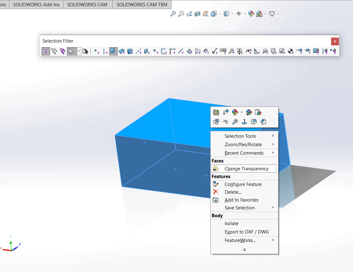
Toggling all the faces to become transparent again will require the use of a selection filter. This can most easily be accessed by pressing the F5 key. It can also be found by navigating to View>Toolbars>Selection filter.
Once the Selection Filter toolbar is up there will be an option to filter for only faces. This will allow for the selection of only faces which is the only way to have the option to toggle the transparency. This is shown below.
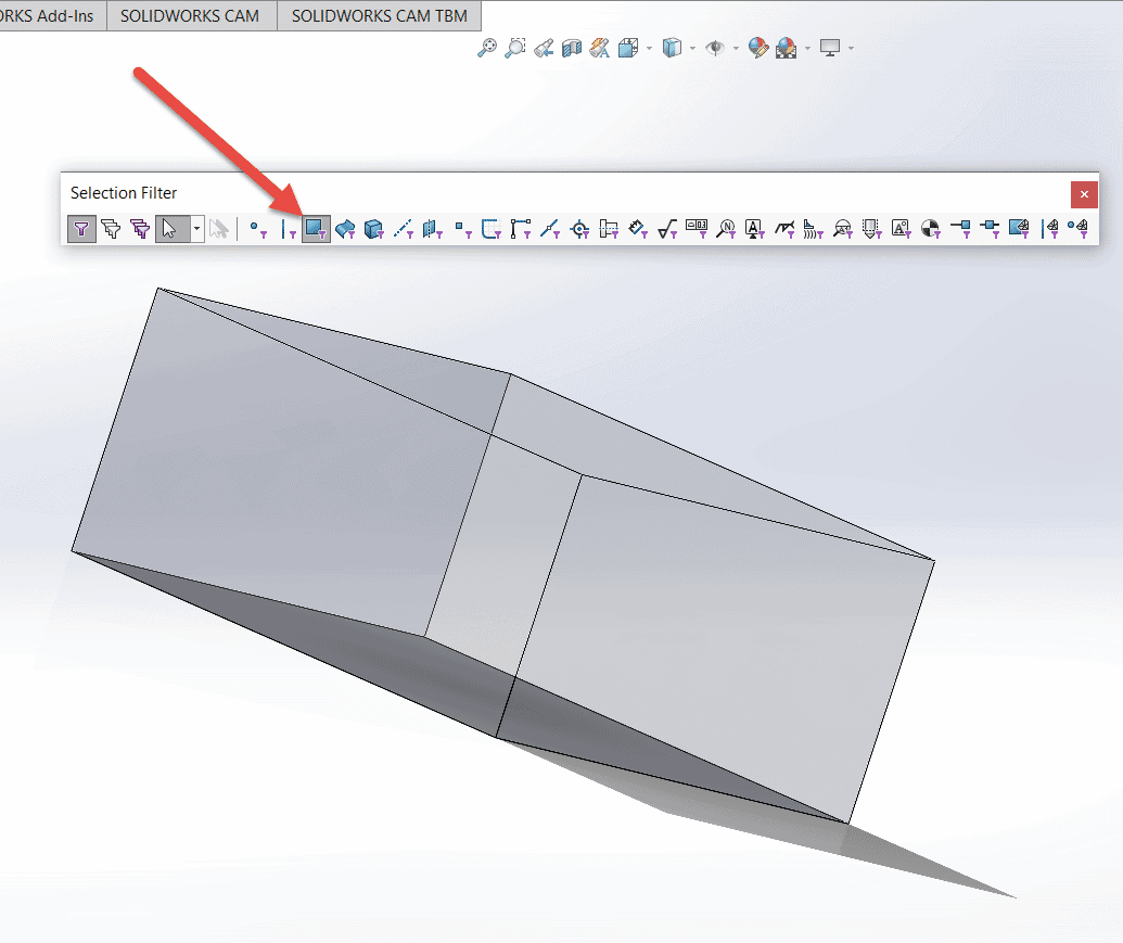
Once the faces filter has been applied, use the command ctrl + a to select all of the faces on the model. Toggling the transparency at this point will either turn all the faces solid or turn them all transparent. Just keep toggling until all the faces have the transparency you desire.
If at this point, if there are still some faces that are having issues with transparency, take a close look at your appearances. The SOLIDWORKS appearance hierarchy is as follows:
- A face’s appearance is visible even if its parent feature has an assigned appearance.
- A feature’s appearance is visible even if its parent body has an assigned appearance.
- A body’s appearance is visible even if its parent part has an assigned appearance.
- A component appearance (assemblies only) overrides all appearance assignments in the component’s faces, features, bodies, or parts.
Hope we’ve helped make things clear(or unclear) for you! If you need further assistance don’t hesitate to contact our technical team.
Beau Hansen
Support Engineer
Computer Aided Technology, Inc.