SOLIDWORKS Simulation – Snap Fit Design and Optimization
Snap-fits are used now-a-days everywhere from remote controllers to pen caps and have many variations including cantilever, annular, and torsional snaps. They can be used to increase assembly speed and have the added benefit of less loose parts.
Where do we start when a snap design is desired? For example, this is a mounting bracket for an electrical control panel:
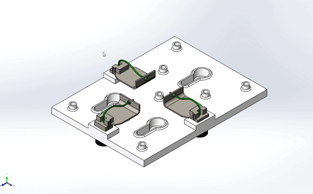
The 3 female connectors must be attached quickly for fast assembly but also need to be secure and able to detach quickly incase of an emergency. There are some industry accepted equations available online that can help with ball-park dimensioning, but my personal favorite approach is to use SOLIDWORKS Simulation to run a linear static study since this is best practice before running a nonlinear static study anyway.
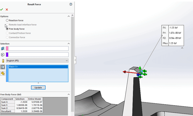
I decided on a cantilever snap, one of the more common snap-fits, but whichever type of snap you decide on I recommend starting with a coarse mesh for fast solving times to narrow down the rough design – fail fast and fail frugal. After a few quick size modifications, the bending stresses yield a F.o.S. (Factor of Safety) equal to 3 and reaction force equal to 1.35 lbf. 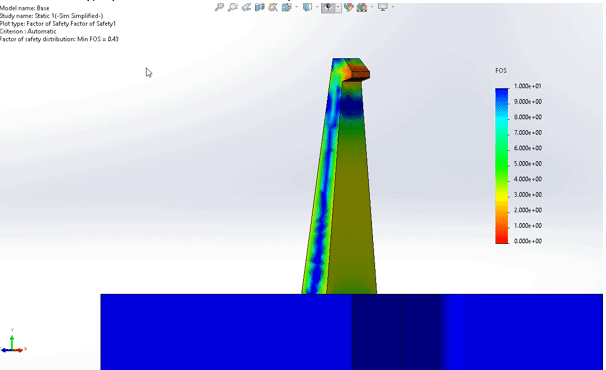
Note that the FoS is less than 1 at the snap head. This is because of the boundary condition that was applied and can be ignored.
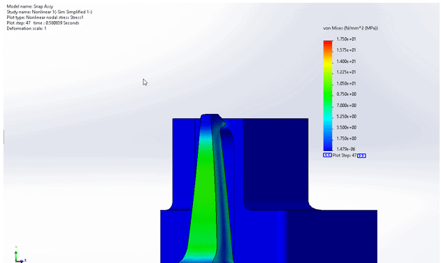
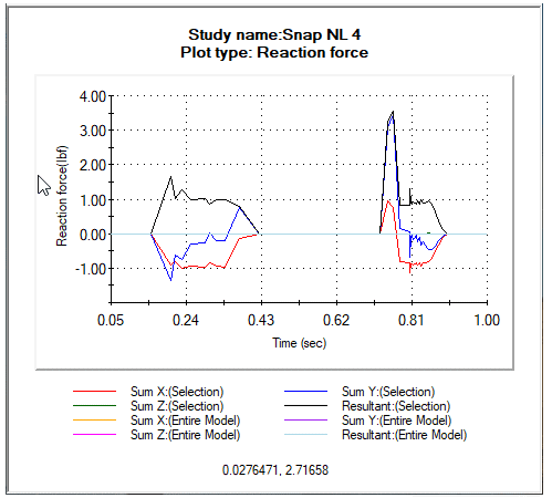
Once these results look good, we can move on to a nonlinear analysis where the real magic happens.
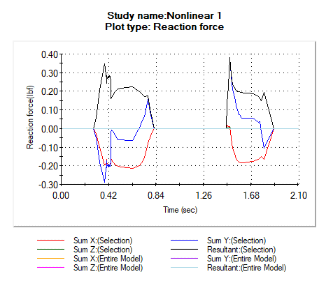
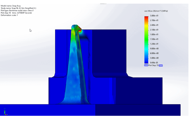
The first run shows stresses well below yield (30 MPa). The only problem is the snap force (in and out), as shown below, is less than 1 lbf.
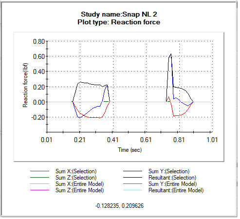
The mating forces for the second design look much better, but the contact stresses are too high, and the magnitudes of the forces are too low. This will result in a loose fit for the electrical connector.
By the fourth iteration I was able to hit my design parameters.
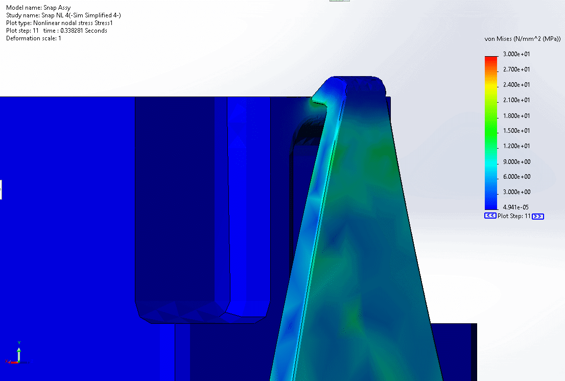
Now that the force to engage each snap is 1.5 lbf and greater than 3 lbf to disengage we can move forward with testing.
A few tips for running nonlinear analyses on snaps:
- Make fillets as big as possible to reduce stress concentrations
- Apply a fine mesh on no-penetration contacts, fillets, and small features
- Changing the width of the snap will increase/decrease the mating force without affecting the stress.
- Make the snap geometry closest to the head flexible and stiff near the base
- If the solver is failing on the first step, try pushing the parts apart to get the solver started before parts are in contact
- Toggling the ‘Large strain option’ on/off can help with solver errors
- Switching the ‘Iterative technique’ to Modified Newton-Raphson may help the solver if none of the above suggestions work
Thanks for reading, be sure to check back for more SOLIDWORKS Simulation blogs.
Cameron Bennethum
Support Engineer – Simulation
Computer Aided Technology, Inc.