Creating Custom Displacement Maps for Natural & Organic Geometry in SOLIDWORKS
In the last blog post we discussed the ability to apply and manipulate 3D textures in SOLIDWORKS to create more natural and organic shapes. In this continuation, we will discuss creating your own 3D textures to create more custom geometry. To get caught up on how to apply 3D textures check out the previous blog post in this series.
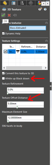
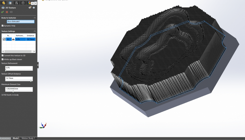
The most important thing to keep in mind when creating 3D textures is that when SOLIDWORKS applies the texture, different heights are assigned to different colors. To make this process simple, use greyscale images. SOLIDWORKS will assign the height to either the darker or lighter portions of the image depending on what is selected in the “3D textures” feature settings, shown in the figure below.
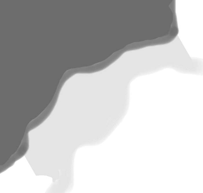
Let’s look at an example to get a better idea. This image was used to create the “Clay” pieces for the board game The Settlers of Catan.
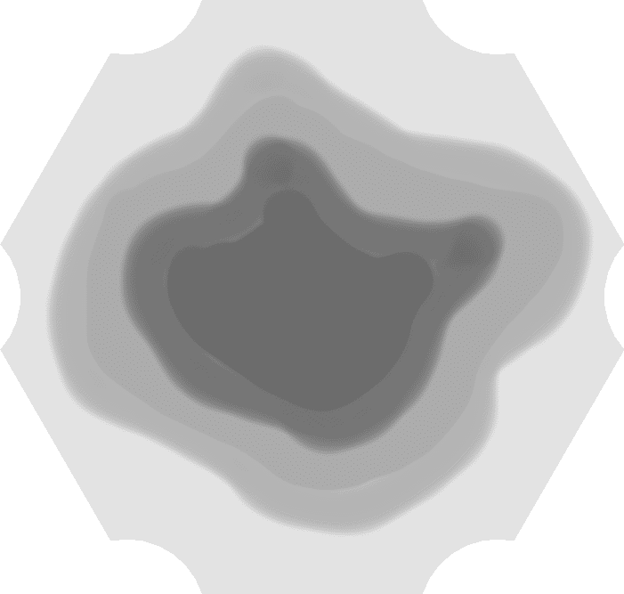
In this case, the image was the exact shape of the part. This is the first step to creating a custom 3D texture. Making the image the exact size will let you control the size and proportions of the texture much easier. Using a layered imaging tool to do this is highly recommended. Photoshop is a good option, but for those looking for a much cheaper alternative, GIMP is a free and open-source image editor.
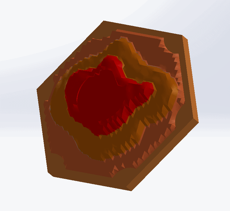
This image was created around the assumption that black would control the height, which means the checkbox in the SOLIDWORKS “3D Texture” box above would remain unchecked. When the texture above is applied to one of the board game pieces, this is the result.
To start a custom texture, get the measurements of the part and create a blank image in GIMP with those measurements. From here, experience with layered imaging tools will determine how easy the creation of the texture is. Some very useful tools include:
- “Magic Wand” tool (Fuzzy Select in GIMP): Allows for mass select areas in an image with similar color. Useful for removing backgrounds.
- Gradient tool: Can create gradients that transition from white to black to create smooth transitions in the texture.
- Layers: Dividing an image into layers allows for background and completed portions of an image to remain visible without editing them.
With these tools, the creation of many different geometries is possible. Below are some examples I used for creating the clay structures.
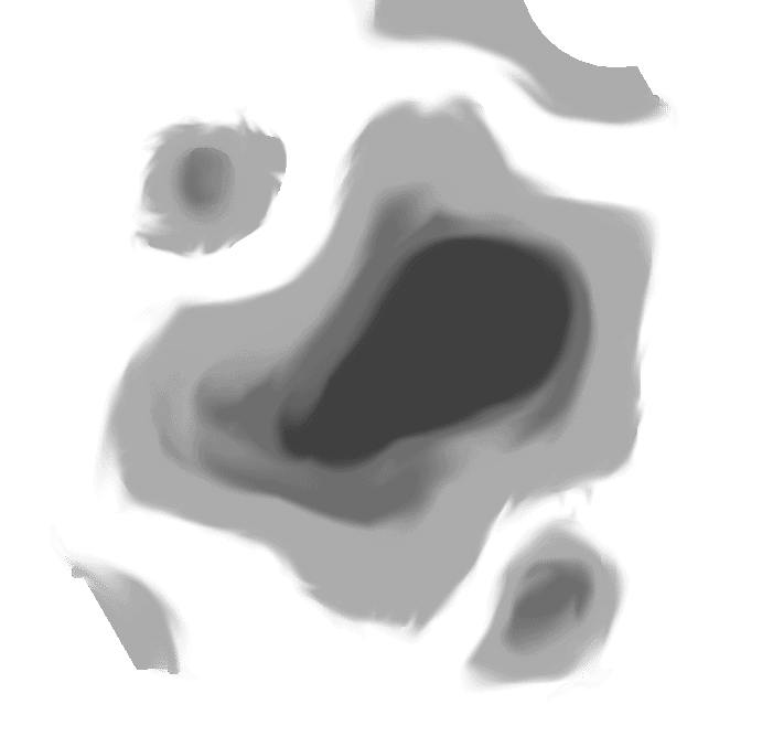
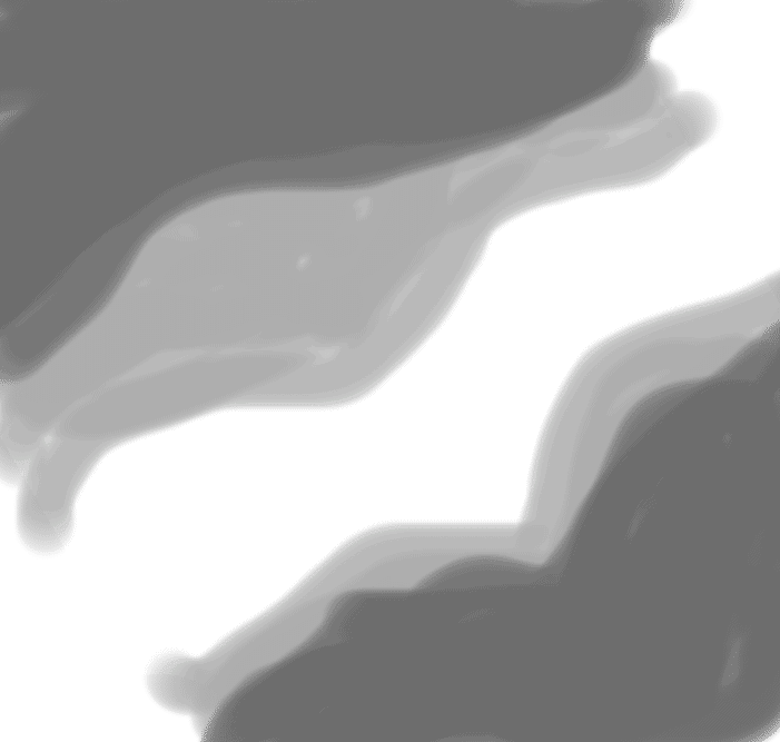
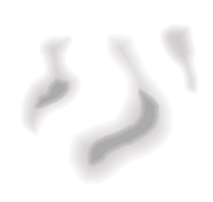
All of these images represent something called “displacement maps” or “height maps” used commonly in 3D rendering applications. Many times these are realistic images like sand or water, however, any image can be used. In the next post these realistic images will be utilized.
Now let’s apply the image! Go through the same process of applying a texture from the previous post. Once the texture is applied, change the image using the “Image” section of the “Texture” box.
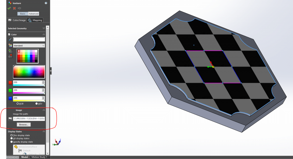
With your image chosen, make sure the scaling is set correctly.
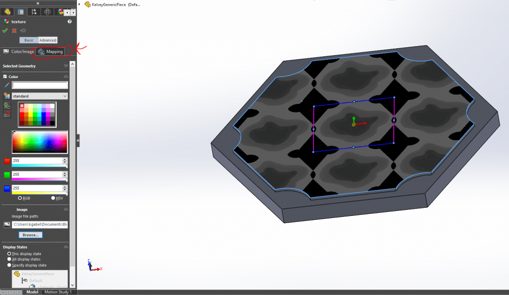
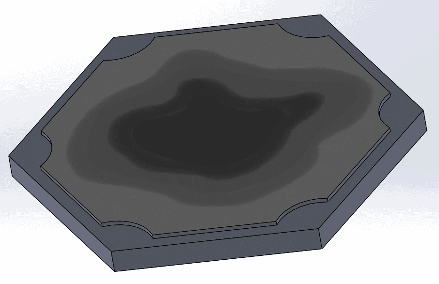
This image was designed to fit perfectly on the face of the piece. The image can be scaled using the corners of the pink & blue box. For more placement tools go in the “Mapping” tab near the top of the “texture” box (you can swap to “Advanced” mode for advanced placement tools). Once the image is scaled properly, click the green check. Properly scaled, this is the look of the Catan piece.
From here, go through the “3D texture” instructions laid out in the previous blog.
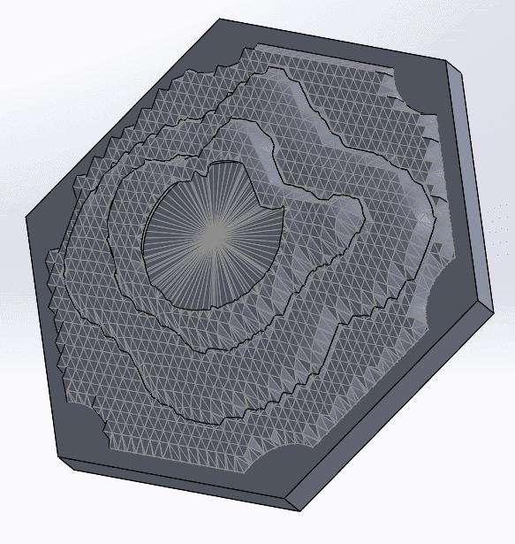
Once the “3D texture” box is open, now is the time to get creative! The “Maximum Element Size” box is going to control how fine the mesh is. Courser meshes will allow for the general shape to appear while very tight meshes will show every stroke of the brush in the image.

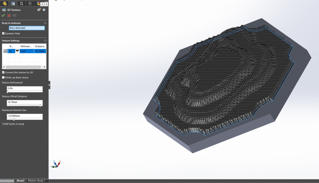
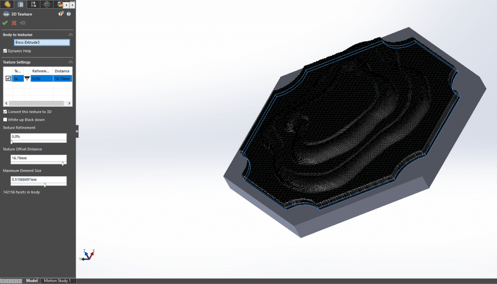
This is also where the controls for the “Texture Offset Distance” (the maximum height) and whether White is up or Black is up. Below is an example of swapping that setting.
Once the desired offset distance and element size have been set, convert the 3D texture into a mesh (instructions in the previous post).Then comes the decision on splitting the mesh into solid bodies. Creating separate solid bodies is one of the easiest ways to color parts for 3D printing in the GrabCAD Print software.
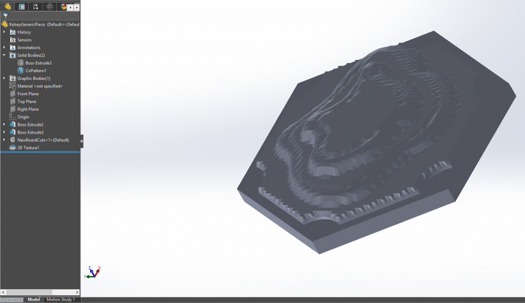
For this part, planes were created to split the different levels of the hill. The process of splitting the solid bodies is outlined in the previous blog post. Once cut into different levels, the circular slot for the board game token. The result is shown below.
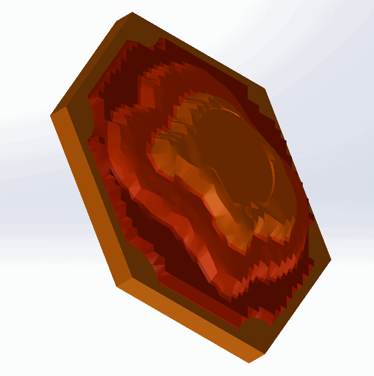
Colors can be added in SOLIDWORKS to get a better idea of what the part can look like.
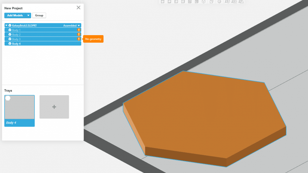
Unfortunately, when the SLDPRT file is inserted into GrabCAD, the beautiful mesh hills are nowhere to be found!
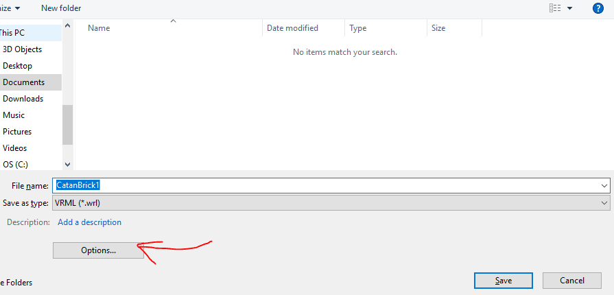
The reason behind this issue is still unknown, but one of the ways around this is to export the SLDPRT file in SOLIDWORKS as a different file type. The VRML filetype is a good candidate for this part. In SOLIDWORKS, save the part as a VRML, making sure to check “Options”.
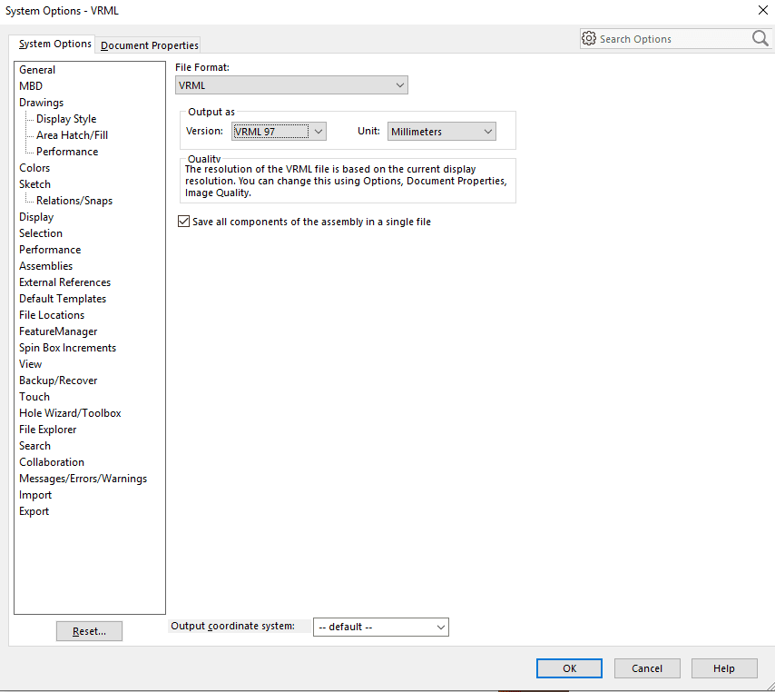
GrabCAD Print only accepts VRMLs in the VRML 97 format. The VRML files can get large depending on the size of the mesh, so the saving procedure may take some time.
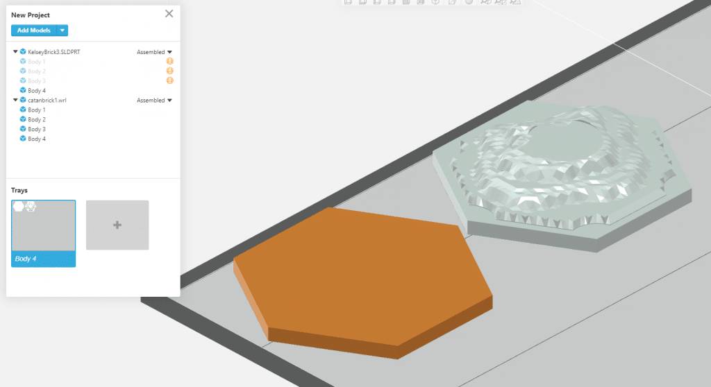
Importing the VRML into GrabCAD gives the expected result.
From here, colors need assigned and then the print can commence! Below is the final printed part.
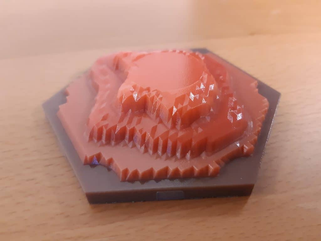
Here are some pictures of the different clay terrain tiles created using this process. Try comparing the displacement maps from earlier in the post and match them to the real parts.
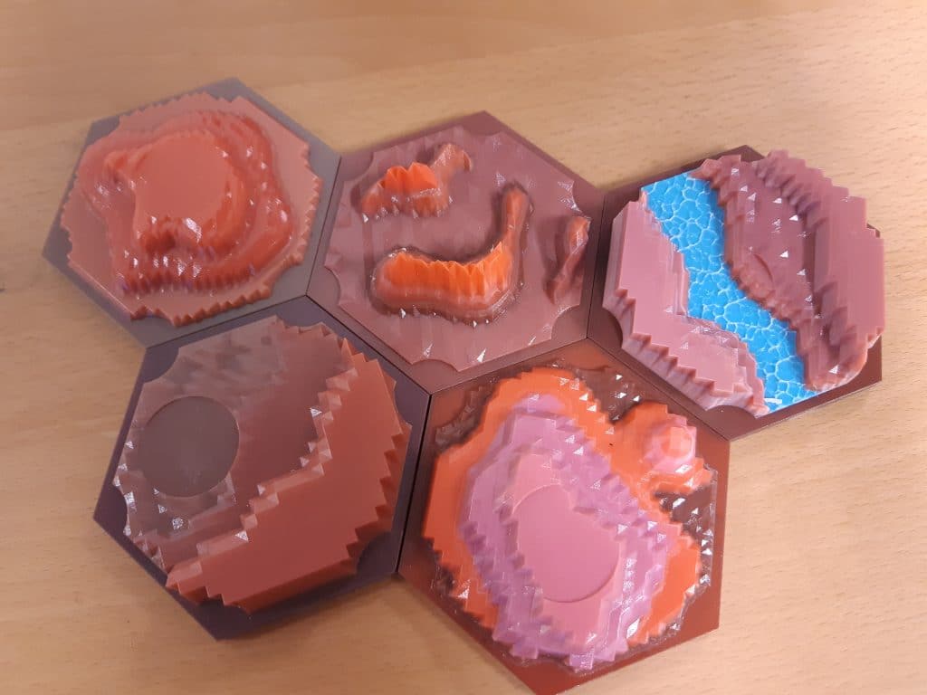
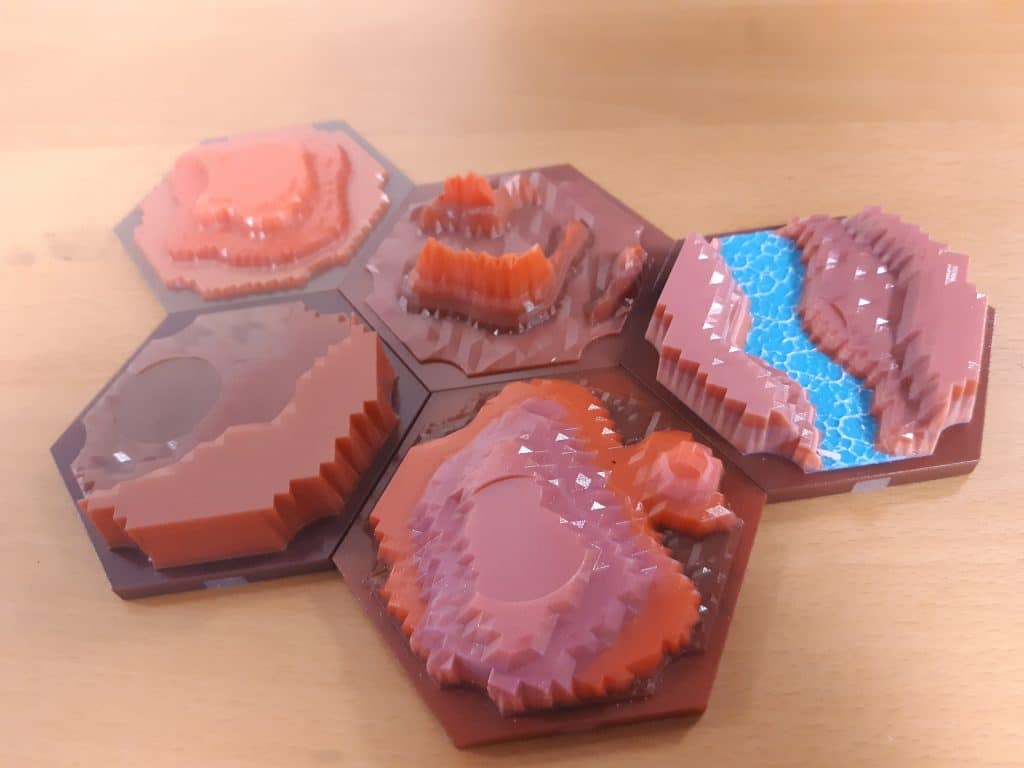
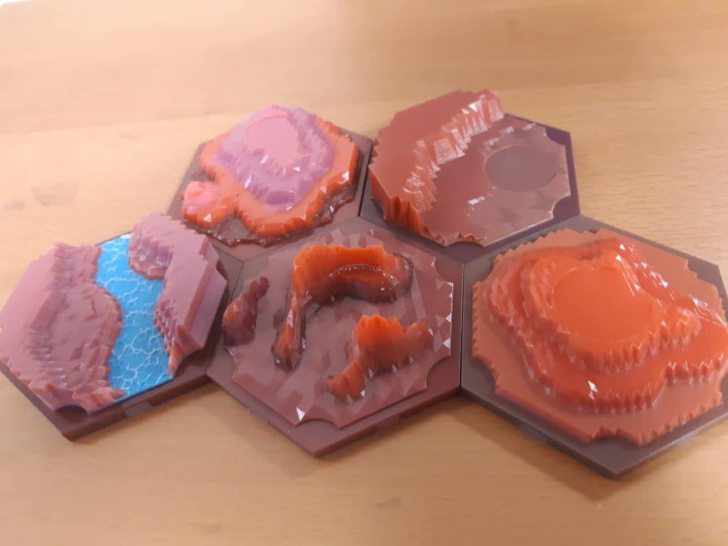
The next post in the series will cover using a combination of custom displacement maps with images from real life (see the river in the photos above).
Until next time!
Kelsey Gabel
Application Engineer
Computer Aided Technology, Inc