SOLIDWORKS Simulation: Thick versus Thin Shell Elements.
How often do you find yourself using SOLIDWORKS Simulation with shell elements and ask yourself, what in the world is the real difference between the Thin and Thick option in the Shell Definition property manager? Is it just simply saying to yourself, well the model I am running an analysis on looks pretty thin to me so let’s go with that or is there more to it? Hopefully, I got your attention now so let’s discuss what the Thick and Thin options means in the Shell Definition property manager.
Before we start lets first recap what a shell element is in Finite Element Analysis (FEA). Shell elements in SOLIDWORKS Simulation are in the shape of a triangle and are used to mesh a surface of the geometry. The element can be of first or second order. First order shell elements, also called Draft Quality shell elements, have three corner nodes with six degrees of freedom per node and remain linear through deformation. Second order shell elements, also known as High Quality shell elements, have six nodes – three corner nodes and three mid-side nodes – that can better map curvilinear shapes.
Now that we have recapped what a shell element is let’s talk about the value of using them when doing FEA. Two big things we all would like to know right before we hit the run analysis button is how long will this take and how accurate will the results be. Since shell elements are two dimensional, your analysis runs will tend to finish quickly. Also, instead of directly capturing the geometry, the shell element formulation includes the thickness information, which is entered during the definition of the shell that will be meshed. This ensures the accuracy of the analysis.
Let’s now get into what this blog is all about and that is what is the difference between the Thick and Thin options, and which one should you use to run an FEA analysis. For those who design parts that are long and thin you were probably trained to right click on the part in the simulation study tree and choose “Define Shell By Selected Faces” which would then make the part to be analyzed as a shell element. See Figure 1 below. From there the Shell Definition property manager would pop up and then you were asked to choose a type. The types to choose from are Thin, Thick, and Composite. See Figure 2 below. The type called “Thin” is mostly used when the shear stress is negligible through the thickness, which is Kirchhoff’s theory where the cross-section perpendicular to the midplane remains straight & perpendicular to the midplane at the end of the deformation. As a consequence, it will ignore the shear deformation and stress in the through-thickness direction. The type called “Thick” follows the Mindlin theory. It assumes the same as a thin shell, but the cross section is no longer perpendicular to the deformed midplane. Thicker shells where shear effects become noticeable can be accurately modeled using this style element. See Figure 3 below. Please note the Thin and Thick options in the Shell Definition manager have no effect on the geometry, just on how shear stress is computed. The Composite option type is not covered in this blog, but if you’re curious, this option defines shells as a composite laminate.
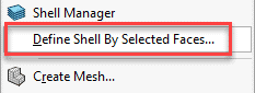
Fig. 1 Option to choose after right clicking on part
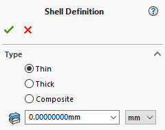
Fig. 2 Shell Definition property manager
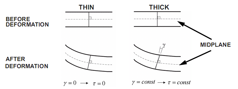
Fig. 3 Thin versus Thick before and after deformation info
Now that we know the difference between shell types lets now discuss how to choose the correct type. In Figure 4 you will see a range of dimensional ratios. The “L” is a characteristic length of the part and “t” is the thickness of the part. This gives a good rule of thumb to use when making your choice.
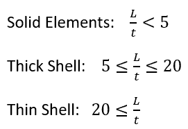
Fig. 4 Ratio formulation
Hopefully after reading this you have a better understanding of the difference between the Thin and Thick types in the Shell Definition manager and now know which shell type to choose for your SOLIDWORKS Simulation runs.
Nick Pusateri, CSWE, CSWP-S, CSWS-S
Application Engineer
Computer Aided Technology, LLC