SOLIDWORKS: Design Study without using Simulation
Have you ever asked yourself, while designing your parts or assemblies in SOLIDWORKS, what would be the most optimal design to minimize the weight or find where the volume is the least in your designs without the use of simulation? Maybe you are even looking for a way to gain insight into finding the relation between your dependent and independent design variables of your designs without using simulation. Well, guess what, SOLIDWORKS can help with that using a tool called “Design Study” which is free in all seats of SOLIDWORKS. So hopefully after reviewing this blog you will see the great value in using the Design Study tool to achieve those types of goals.
Before we start lets first define what a Design Study is in SOLIDWORKS. A Design Study is used to evaluate and optimize your parts and assemblies. Evaluation and Optimization are the two main modes for running a Design Study. The Evaluation mode is when you specify discrete values for each design variable and use sensors as constraints. The software runs the study using various combinations of the values and reports the output for each combination. The Optimization mode is when you specify values for each design variable either as discrete values or as a range. You use sensors as constraints and as goals. The software runs iterations of the values and reports the optimum combination of values to meet your specified goal. If you would like to learn more about sensors SOLIDWORKS then refer to a blog we did a few years ago called Sensors in SOLIDWORKS.
Now that we have defined what a Design Study is let’s next see how to actually use this tool on a bottled designed in SOLIDWORKS. In Figure 1 below you will see that the bottled was designed using the multibody method. We also named some dimensions that will be used for our Design Study. The “Intersect” feature was also used to create an internal body to also be used in the Design Study. To learn more on how to use the Intersect feature in SOLIDWORKS then refer to a blog we did a few years called Creating Internal Volume – Intersect. Next, we will turn on the Design Study tool by going to the Evaluate command manager tab and choosing the far-left icon called Design Study. See Figure 2 below.
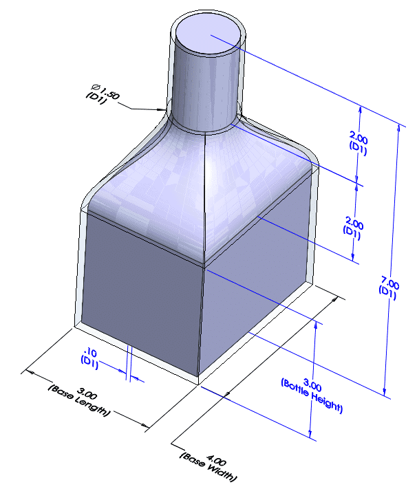
Fig. 1 Multibody bottle design

Fig. 2 Design Study icon
Exploring the Design Study Properties
With the Design Tool now turned on lets now talk a little about what all the options mean. If we choose the Design Study Properties icon you will see it leads to a property manager where you can choose the type of study quality to be used, where the results can be saved, motions study options, and notification settings. See Figure 3 and 4 below. When it comes to choosing the study type you first need to determine if you are going to run an Optimization or an Evaluation Design Study. Once you determine the type then you will need to address the variable type to be used for the study type. Variable types to choose from are either Continuous, Discrete, or a combination of both. Click on this link to go to the SOLIDWORKS Help page that goes into more detail of what a High Quality and Fast Result study does for both Optimization and Evaluation types studies.
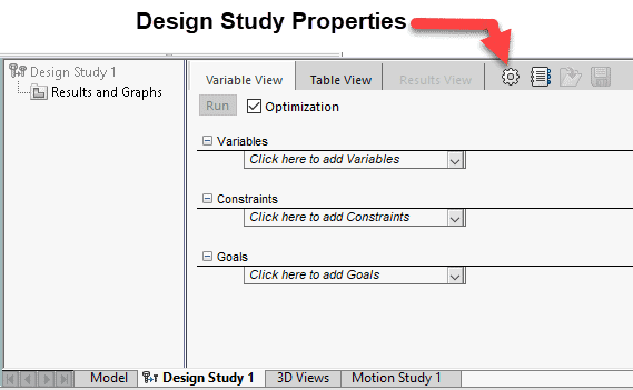
Fig. 3 Design Study creator
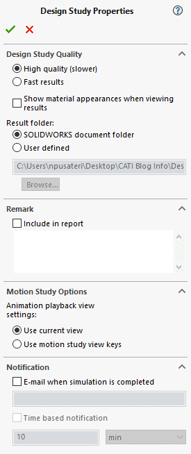
Fig. 4 Design Study property manager
The Design Study creator interface has three tabs to choose from which are Variable, Table, and Results View. The Variable and Table tabs are where you set up your parameters, constraints, and goals. See Figures 5 and 6 below. When you have a goal set up then that allows you to use the optimization option for the study. The Results View tab is simple reviewing the results of the scenarios that have been run. In Figures 7 and 8 you will see the types of sensors that can be created as well as the types of settings there are for variables, constraints, and goals.
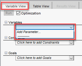
Fig. 5 Variable vs Table view
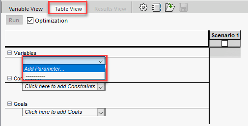
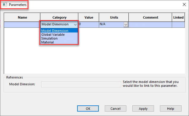
Fig. 6 Parameters property manager
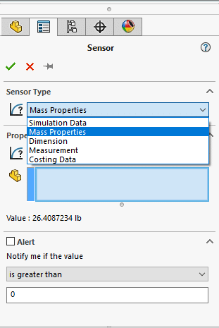
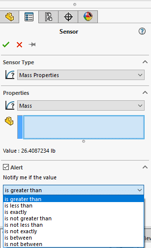
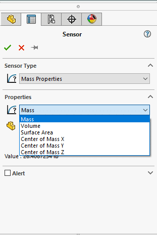
Fig. 7 Sensor Type property manager
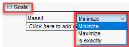
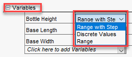
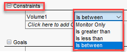
Fig. 8 Setting listings
For the bottle design, we chose three dimensions to vary between a min and max value. We set up a constraint of the internal volume to be between a certain min and max value by the use of a volume sensor. Lastly, we chose to have a goal for the mass to be minimized using a Mass sensor. Once we set all the parameters up the Design Study creator will then display the total number of scenarios it will need to run based on the parameters you set up. In this case we have a total of nine to be solved. See Figure 9 below.
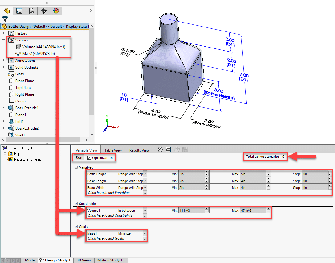
Fig. 9 Parameter settings of the Bottle design
After setting up all our parameters we would then hit the Run button to run all nine scenarios to then display three types of results under the Results View tab. See Figure 10 below. You can click on any of these columns to display the model per whatever values are listed in the column. The green column indicates the best optimal scenario. The red column(s) indicates violation of one or more constraints by the scenarios that were ran. Columns that have the user interface background color with black letters and numbers indicates scenarios that are not optimal or faulty. Columns that have the user interface background color with grayed out words and numbers indicate failure to rebuild the scenario.
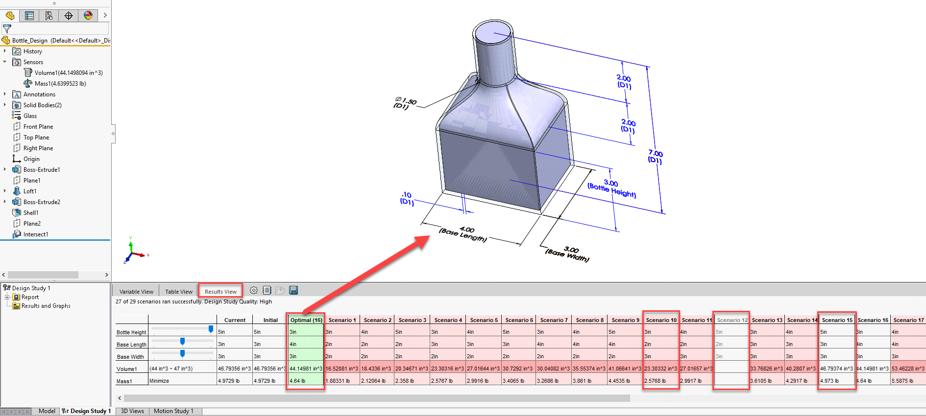
Fig. 10 Results View
If you right click on the “Results and Graphs” folder you will see a few options to choose from. See Figure 11 below. One option will purge your previously ran scenarios so you can start over. The Define Design History Graph option lets you plot a 2D graph of a design variable, objective (goal), or constraint with respect to the scenario number. The graph is not available if you use continuous variables. The Define Local Trend Graph option lets you plot a 2D graph of an objective (goal) or a constraint with respect to a design variable. The graph is not available if you use discrete variables and select High Quality for the study quality.
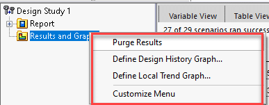
Fig. 11 Results and Graphs folder options
Lastly when you finish a Design Study in SOLIDWORKS you can create a Word Doc style report to document all aspects of a study. See Figures 12 and 13 below.
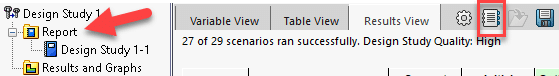
Fig. 12 Design Study tree saved report location
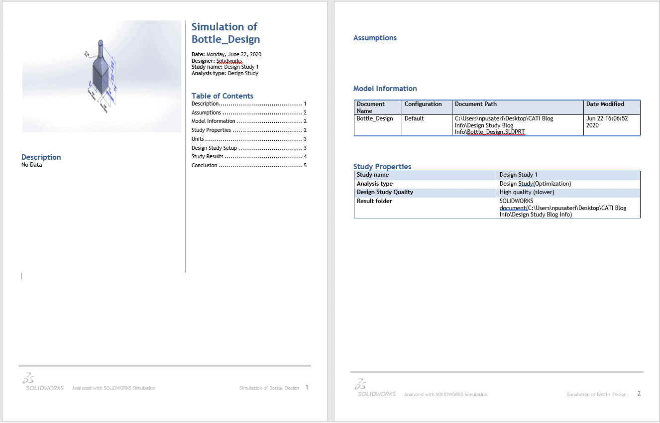
Fig. 13 Design Study report example
Hopefully after reading this you will start to use the Design Study tool in SOLIDWORKS on the designs you do at work. The Design Study tool is a great way to evaluate and or optimize your designs to find the most optimal or best design(s) per whatever goals you set out to achieve.
Nick Pusateri, CSWE
Application Engineer
Computer Aided Technology, Inc.