Configure Your Assembly with SOLIDWORKS Electrical: Excel Automation
Yes, you read that correctly. We are going to use SOLIDWORKS Electrical Schematic to configure our mechanical assembly. SOLIDWORKS Electrical is a collaborative design tool that allows you to build a project across both the mechanical and electrical design environments. This collaboration allows you to parametrically build and edit a project from either discipline instead of creating independent documents that go toward a finished project. This level of collaboration requires SOLIDWORKS Electrical Schematic Professional, SOLIDWORKS Electrical 3D, and any seat of SOLIDWORKS mechanical.
Since we can build a project from information added by electrical or mechanical users, why not use some automation techniques in SOLIDWORKS Electrical in order to help us with our mechanical assembly? SOLIDWORKS Electrical has a tool called Excel automation that allows you to create and configure projects based on filling out a form. We can use this technology to configure our mechanical assembly as well.
The key to using Excel automation to automate the assembly is the use of permanent components. A permanent component can exist in a project even when it is not documented on a schematic. This means we can create an assembly with every variation of every component in it and link the models to permanent components in an empty electrical project. We can then set this project to a template and configure Excel automation to do the work for us.
Lets see this in action.
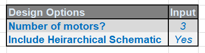
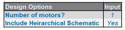
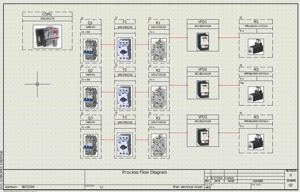
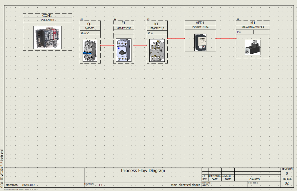
We can treat Excel like a form to drive any necessary schematic/BOM information required for a project. Here I specify a configuration for a 3 motor electrical system and 1 motor system. This form will drive all the macro library elements necessary and piece my schematic together.
3 Motor System
1 Motor System
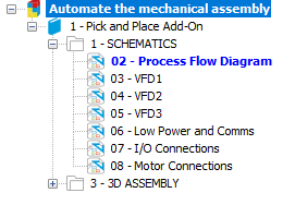
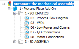
Next we can run Excel automation in our empty schematic project that is linked to our filled out assembly. As you can see, Excel automation was able to draw all the necessary items required based on our form inputs.
At this point, we can run some clean up processes such as re-number documents and components, and now our BOM and routing information is ready to go.
Now on to 3D. If we turn off the permanent components, only the objects that are represented on the schematic will remain.
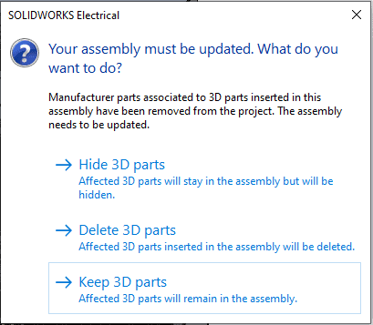
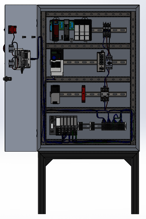
When opening the assembly linked to the electrical project and by selecting to “Delete the 3D parts” that are no longer associated to components, we will end up with the following result:
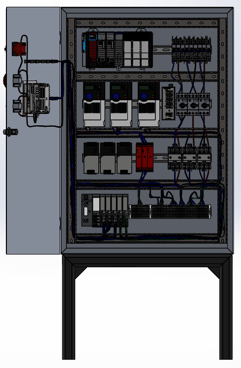
Thus we have configured our assembly according to our automated schematic using Excel automation. We can rest assured that we are working with a unified environment between electrical and mechanical, and we can literally generate our needed project information as orders come in. This process can be automated even further by using SOLIDWORKS configurations, Driveworks, or custom electrical API as desired until our documentation is fully automated and error free giving us the time to do what we do best, design and invent.
Mark Talbott
Sr. Application Engineer Specialist, Electrical
Computer Aided Technology, Inc.