SOLIDWORKS 2021 What’s New – New Spacing Options for Chain Component Patterns
SOLIDWORKS 2021 introduces a new way to control the “Distance” and “Distance Linkage” Pitch Methods in the Chain Component Pattern command. In the updated PropertyManager, you can define whether you want the spacing between components to be measured along the path or along a straight line connecting the components. These two conditions are referred to as “Distance along path” and “Linear distance,” respectively, as seen in the image below.
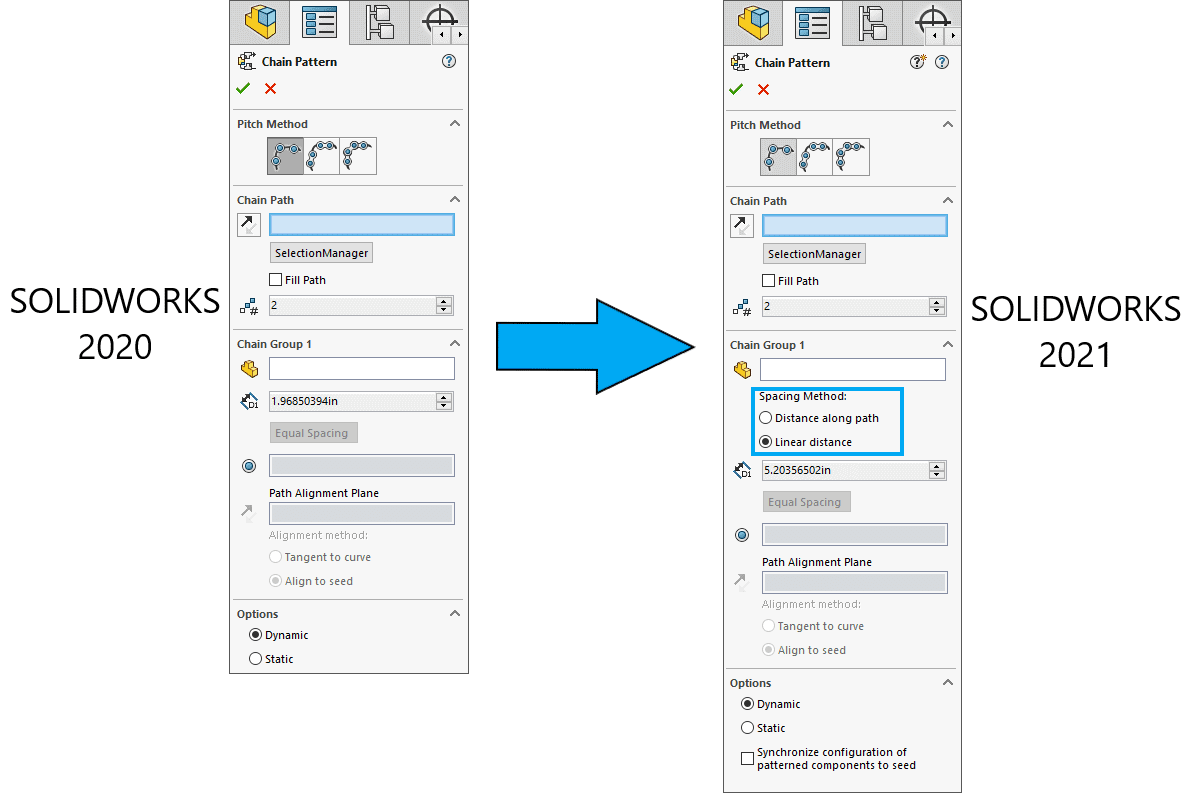
In past versions of SOLIDWORKS, users lacked the ability to specify how the distance from one component to the next was calculated. The spacing defined in the PropertyManager corresponded to the linear center-to-center distance between consecutive links; in other words, all Chain Component Patterns prior to SOLIDWORKS 2021 used “Linear distance” spacing. In some situations, though, it might be more appropriate to evaluate that spacing relative to the path. If the path is straight, the two options will be equivalent, but a curved path will yield different results whether the spacing is measured along the path or linearly.
To demonstrate this difference, I created a part, inserted it into an assembly, and drew out a path sketch for the Chain Component Pattern, as shown below. My component has only one path link, so I will use the “Distance” Pitch Method to define the pattern. That said, as I mentioned before, the new Spacing Method options are available with the “Distance Linkage” Pitch Method as well.
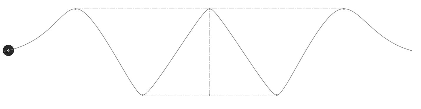
I want the components to be 15” apart from one another. Based on that spacing value, the “Fill Path” option generates as many instances as can fit on the path.
To highlight the difference between “Distance along path” and “Linear distance,” I zoomed in on the left side of the pattern and took screenshots of the region with either Spacing Method. The image below shows the two outcomes, with the orange components representing the “Distance along path” option and the blue components representing the “Linear distance” option.
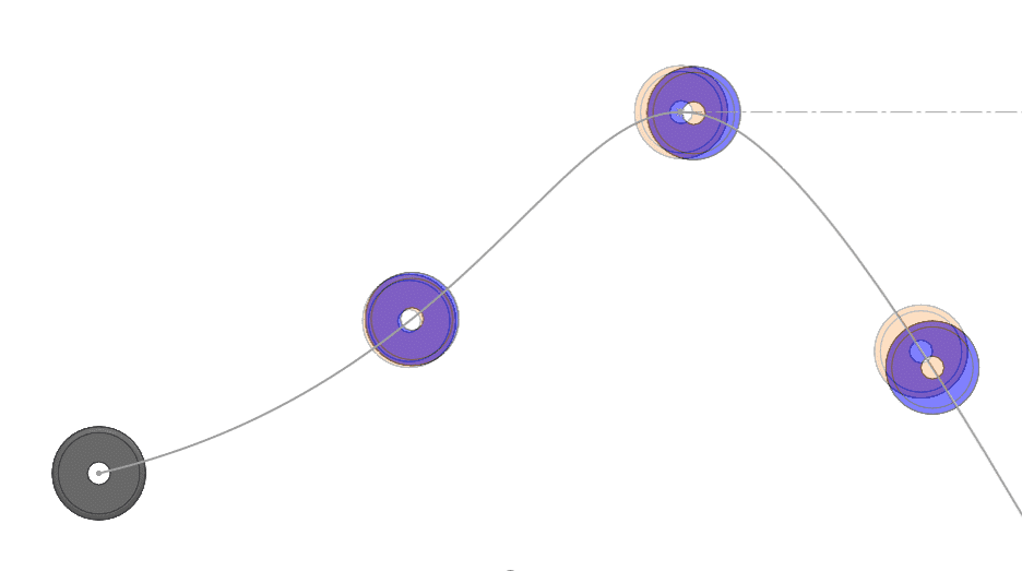
As you can see, the orange components tend to appear slightly ahead of (i.e., closer to the seed than) the blue ones. Again, the orange components were defined with “Distance along path,” so the path length between each instance is 15”. Since the path is curved and thus less direct of a route than a straight line, the center-to-center linear distance between consecutive orange components is less than the path length between them, which is why the orange components appear to be closer to one another than the blue ones.
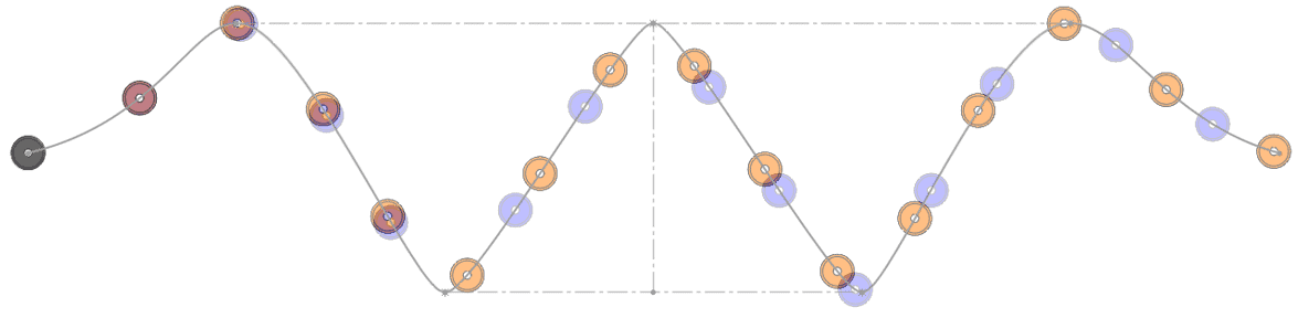
Zooming out to look at the full model, you can see the large-scale effects of the change. The “Distance along path” version of the pattern is able to fit two more components along the chain than the “Linear distance” version. The difference between the two methods is most apparent at the high and low points of the path, where the direction changes most significantly.
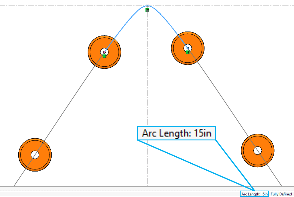
To verify that the distances are correct, there are two approaches. For the “Distance along path” method, I want to make sure that the length of the path between two instances is 15”. I can create a new sketch, use Convert Entities to bring in the path spline, and then drag the endpoints of the spline to align with the centers of the components. When I click on that sketch segment, I get an Arc Length of 15”, as expected.
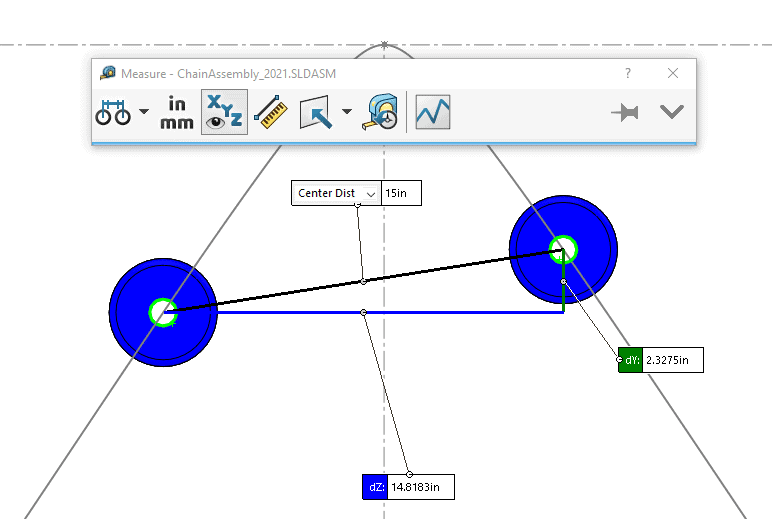
The second approach is more suited for the “Linear distance” method. I can just use the Measure tool to make sure that the center-to-center distance between two blue instances has a magnitude of 15”.
Overall, these new Spacing Methods give you greater control over how the instances in your chain relate to one another. Depending on the number of turns in your path, you can see some drastically different outcomes as you toggle between the two settings, so give both methods a try to figure out which one fits your design best.
In addition to these spacing options, you may also notice that the Chain Component Pattern PropertyManager now has a “Synchronize configuration of patterned components to seed” button at the very bottom. Another enhancement in SOLIDWORKS 2021, this option exists with several assembly pattern types and will be discussed in another blog article in a few weeks. Stay tuned!
I hope this part of the What’s New series gives you a better understanding of the new features and functions of SOLIDWORKS 2021. Please check back to the CATI Blog as the CATI Application Engineers will continue to break down many of the new items in SOLIDWORKS 2021. All these articles will be stored in the category of “SOLIDWORKS What’s New.”
Anthony Sandri
Application Engineer
www.cati.com
What is DI Month? We’re declaring October Design Innovation Month—again! It’s a month-long series of special events focused on what’s new in design and manufacturing technology. You’ll learn about enhancements in SOLIDWORKS 2021 that deliver new capabilities for improved performance, streamlined workflows, and a connected design ecosystem. Find out what’s new in 3D printing applications and 3D scanning to integrate into your design process.