SOLIDWORKS: Custom View Orientation
Sometimes Standard View Orientation, Projected Views or Auxiliary Views will not get you the view results your trying to accomplish. There are other techniques for creating custom view orientation.
- New View
- Relative View
- 3D Drawing View
Let’s take a look how to create these other custom views.
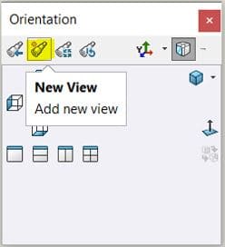
The first custom view is New View. The New View command can be found in the Orientation dialog or in the Heads-up under View Orientation. The New View can be saved and used in a drawing. The reason you may want to create a new view, is a face of a feature may not be orientated on a primary plan. In this example, notice we are looking at the back view and the front plane is the primary plane. The face highlighted is what we want to look at as Normal To.
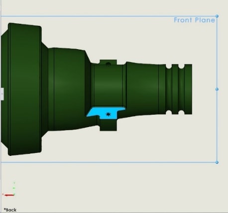
Here is how we create a New View.
Select a face and click Normal To. Press the space bar, the orientation dialog pops up. Click New View.
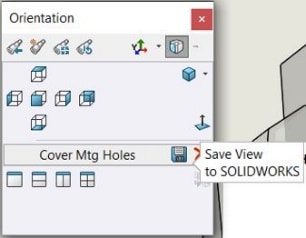
Name the view. I will name mine, Cover Mtg Holes. Press the space bar and notice the new view is added. You can save and delete the view added.
Open the drawing, click view pallet and refresh from the task pane. Notice in the View Pallet the new view is there.
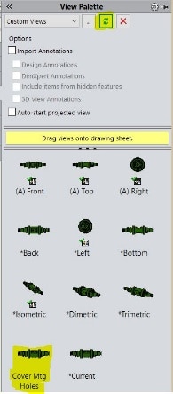
Now you can drag and drop the New View onto the drawing sheet.
The second custom view is Relative View.
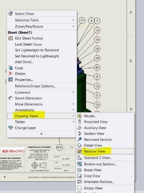
The Relative View command can be launched from the drawing of a part or an assembly. Right click a drawing view or sheet, click Drawing Views and then Relative View.
It will open the model file. Select the face to be orientated (first and second). Your options for both will be primary planes along with some others. I will choose Right and Front for this example.
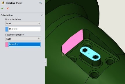
Click the green check mark and place the view.
You can now modify the view as if it were a standard view (section, detail, crop and so on and so forth).
The final custom view is 3D Drawing View.
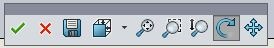
You can access this command in the Heads-up or click View, Modify, 3D Drawing View.
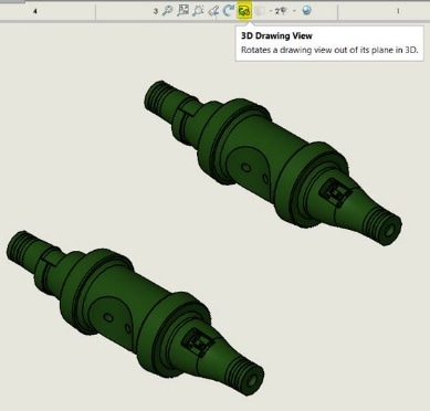
This command allows us to rotate, pan, zoom in and out and a few more options. Like being in the model, except your just using your LMB and hold. Pretty cool right? There is a toolbar associated with this command.
Here we go.
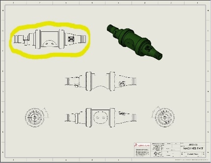
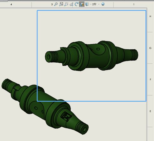
Select the isometric view on the sheet. Click 3D Drawing View and start rotating which is by default.
Standard 3 views can use the 3D Drawing View mode, but will not be able to save or change orientation.
You cannot use 3D Drawing View Mode with Detail, Broken, Cropped… you get the gist.
There you have it. Some great techniques that you can use to accomplish those not so easy view orientations.
Stay safe and have blessed day.
Roger G. Ruffin
Senior Application Engineer
Computer Aided Technology, Inc.