Import your Company Logo Directly into Sketches!
Tired of using sketch pictures and splines to map out your company logo? Can’t find the right font to match? If you have answered “yes” to either of these questions, then you are in the right place.
The process of importing a company logo – or any image, for that matter – is simple and quick. By the end of this article, you will see a process workflow on how to import a picture into a SOLIDWORKS sketch as sketch entities.
In this blog, you will learn how to edit a company logo or photo for proper translation, turn it into a DXF/DWG format, and import it into SOLIDWORKS.
Work smarter, not harder, and start utilizing some of these features to make your designing as efficient as can be.
CONVERTING PHOTOS
Before converting images like logos into DXF formats, picking out the right image is important to ensure that the translation is a success. Personally, I have had most luck with monochromatic photos. Photos with multiple colors have a chance not being translated completely into DXF images.


Left: Image used in converting DXF file. Right: Converted DXF line entities, some edges did not come through the converter.
By using basic photo editing software, I turned the image above into the monochromatic image
pictured below. The conversion recognized all the lines correctly.


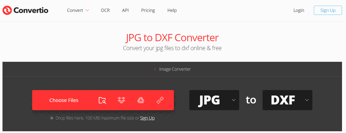
To convert an image like the one seen above, go to any photo or visual editing software. I used Camtasia Studio to get my results. By adjusting the contrast to maximum and the brightness to zero, a silhouette effect is achieved. Saving this as an image file, it is now time to convert the photo into a DXF. I like to use Convertio, but any JPG/PNG-to-DXF converter should do. Be wary of which sites to trust.
IMPORTING PHOTOS
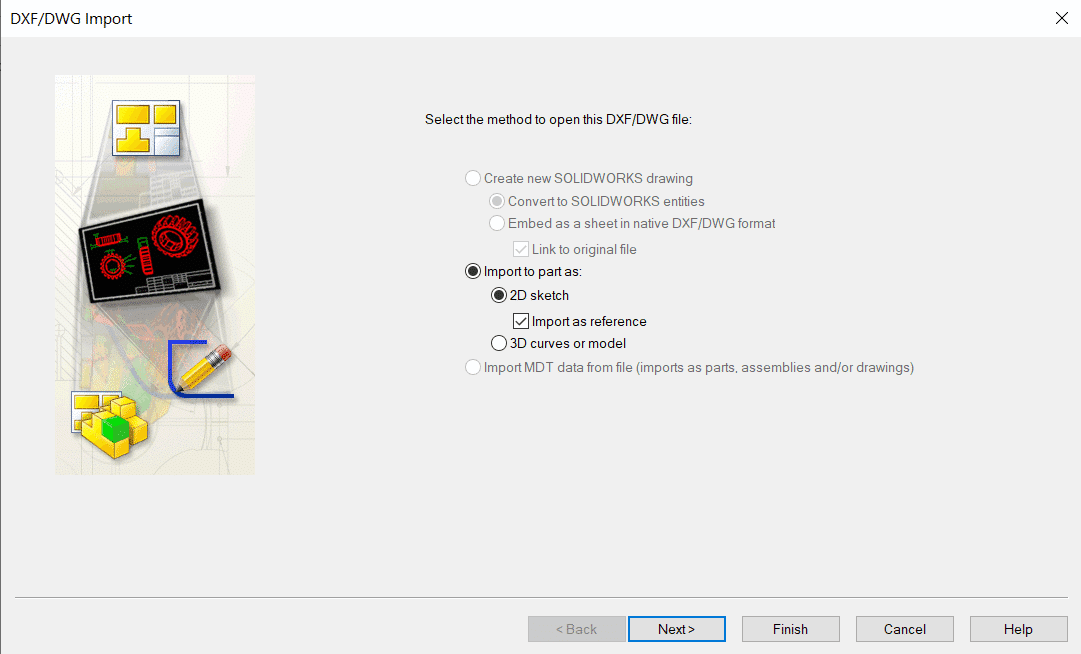
Now that I have a saved DXF file, it is time to load it into the model. Select the preferred face or plane to insert the sketch onto. Then click Insert>> DXF/DWG…
Import to part as 2D Sketch. Import as reference can be checked if desired.
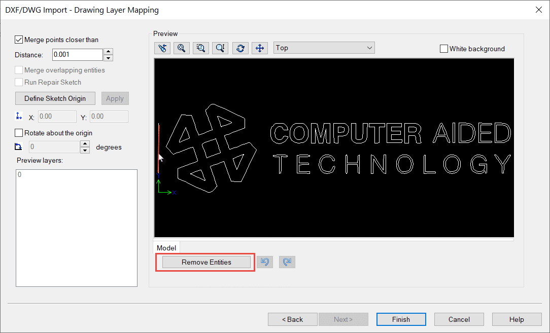
On the next page, options to import layers are given. Just click “Next” here, as the converter will not apply layers to the sketch entities.
The next page is also useful. I can define a sketch origin to be in the middle of the logo for easier centering. I can also remove any unwanted sketch entities by selecting the edge(s) and clicking “Remove Entities”.
For more information on importing DXF/DWG files visit our DXF import blog post.
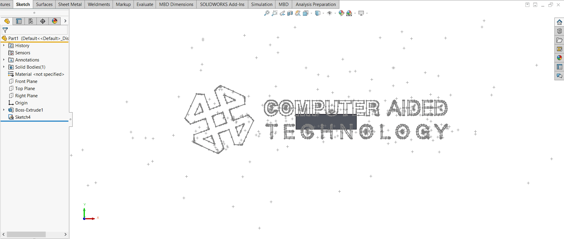
When clicking “Finish”, SOLIDWORKS places a non-editable sketch on the surface plane or face we selected. This is denoted by this symbol:
![]()
The sketch will import with incorrect scaling because the converter cannot measure units from a JPG or PNG file.
Reference sketches cannot be edited without right-clicking the sketch in the Design Tree to make it an editable sketch.
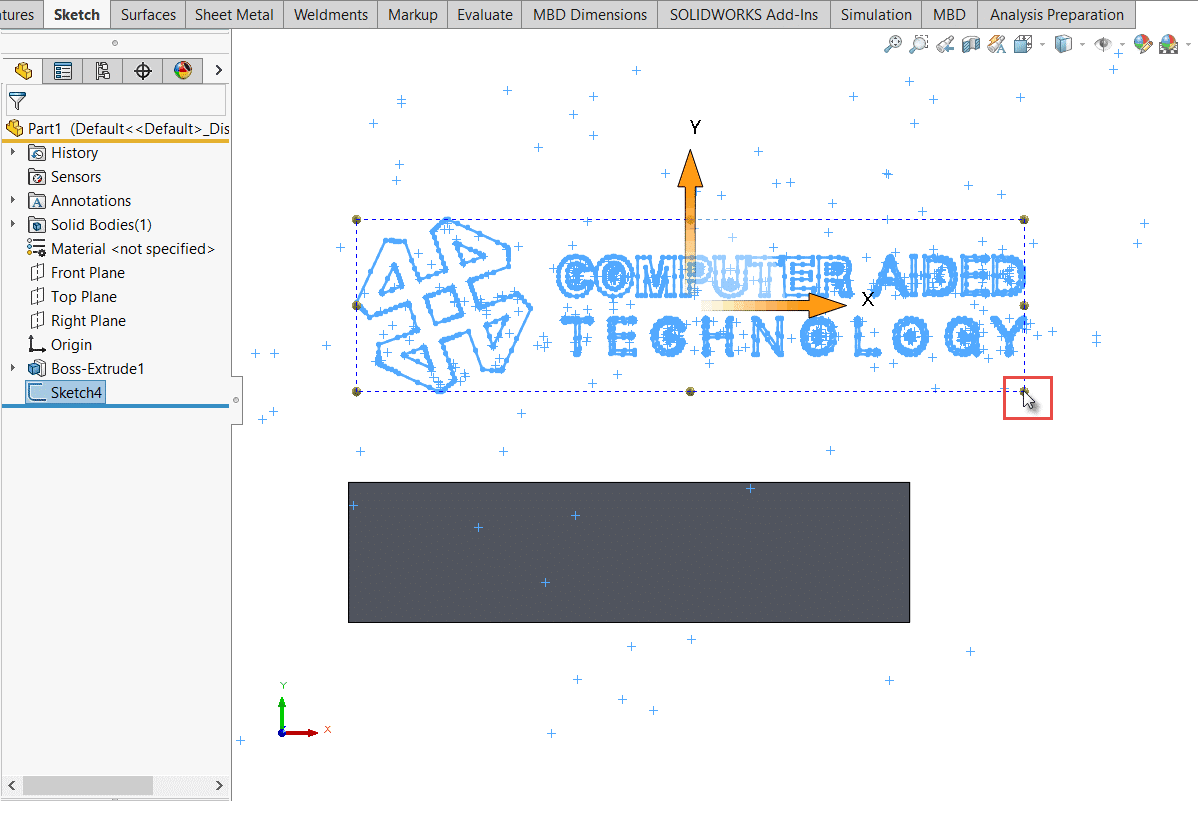
I can “Make Edit Sketch” by using RMB. This allows me to scale and move the sketch. I can use the corner drag points to proportionately size the logo to custom size on this 200mm x 50mm block. Then I can use the X-Y drag handles to locate the sketch on this face.
Once I have it centered on the face, I can use cuts or bosses to extract the 3D feature data! I used this to create a 0.200” inch cut depth.
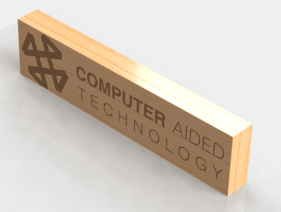
Now I can use the modeled image to generate g-code for CAM machining or laser engraving. The best part? No sketching. No adding relations or adding dimensions. This is an exceptional time saver that you can implement today.
CONCLUSION
Wrapping up, SOLIDWORKS has a variety of tools to aide in sketch creation, such as Sketch Picture and splines. These tools are still quite beneficial in many circumstances. But splines are inefficient and tedious. This photo-converting method can save countless hours and produce more accurate results. With a little technical know-how and novice photo editing skills, we were able to convert our image to monochromatic, translate into a DXF file, and import it into our SOLIDWORKS model without any sketching.
Whether it is an embossed logo on a standard part, or a sheet metal laser-cut pattern, this method is viable and versatile. Give it a shot the next time you attempt a similar task instead of sketch pictures and I am sure you will thank yourself upon completion.
This has been a fun topic to cover. If you have made it this far, thank you, and until next time, HAPPY DESIGNING!
Warm Regards,
Jordan Kleinschmidt, CSWE
Application Engineer
Computer Aided Technology, Inc.