Using Design Tables to Create Tabulated Drawings in SOLIDWORKS
SOLIDWORKS design tables help you to efficiently create and manage model configurations. Leveraging the capabilities of Microsoft Excel, you can easily control design parameters—such as dimensions, suppression states, and materials—through cells in a spreadsheet. Once you have your model fully constructed though, there comes the question of how to clearly represent these distinct configurations in a drawing.
A tabulated drawing is one popular method to detail a family of similar parts. In this kind of document, varying dimension values are replaced in the drawing views by symbols (such as letters or brief descriptions), and a table says what the measurement should be for each symbol depending on the part number. In SOLIDWORKS, a design table can accomplish this same purpose. With some simple modifications, your model’s design table can supplement just a generic set of drawing views to fully describe the entire part family, giving the reader all the information they need to manufacture any member of the family.
As an example, I’ve designed a group of pencils in different lengths. (Honestly, it wasn’t until after I finished the first configuration that I remembered pencils come in basically just two sizes—standard and “golf”—so we’ll just imagine that there are more options for the sake of demonstration.) In the image below, you can see my four configurations: Extra Long, Standard, Golf, and Mini Golf.
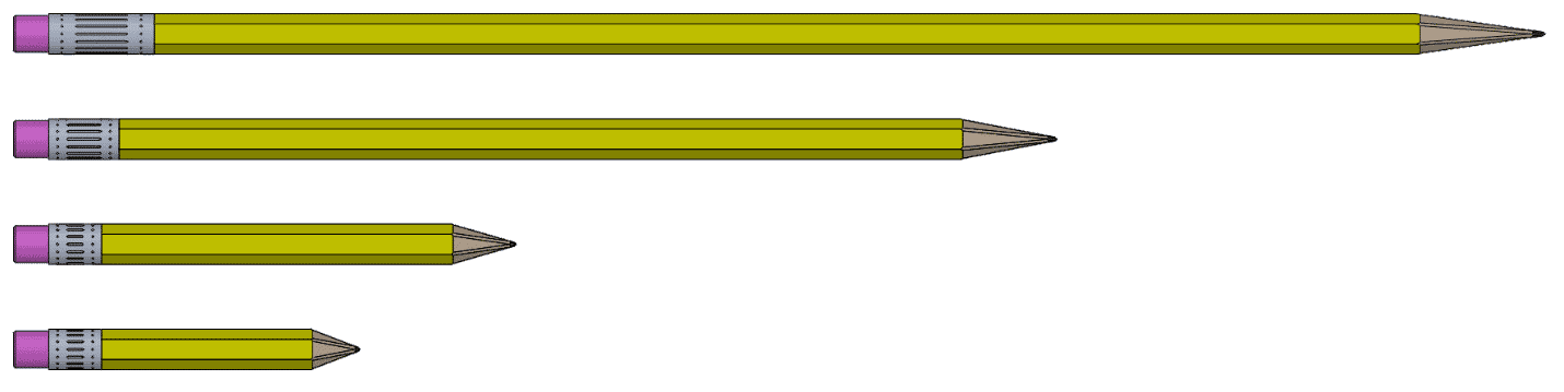
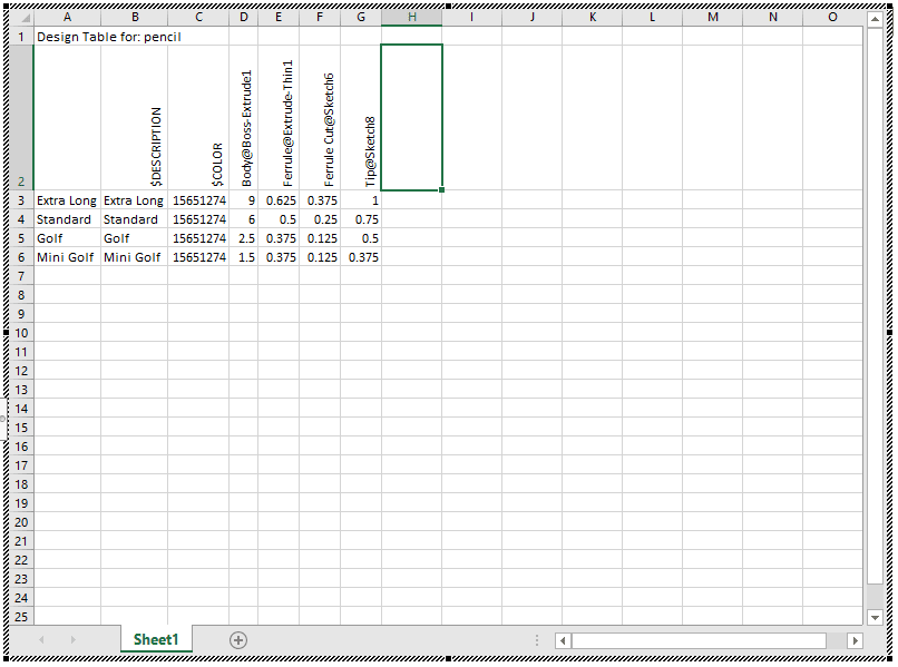
There are four main dimensions in this model that can vary from one configuration to the next. Most notably, the length of the body (the yellow region) changes in each instance. The metal part by the eraser (referred to as the ferrule, I have found out) has two varying dimensions: The lengths of the ferrule and the long notch in it can both change. Finally, the length of the tip is different in each configuration. All four of these dimensions are captured in the design table.
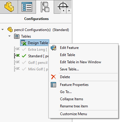
After it’s created, this table can be found in the Tables folder in the part’s ConfigurationManager. Right-clicking it presents you with a few useful options. Edit Feature can be used to modify the table’s properties or to recreate the table by importing an existing file. The Edit Table and Edit Table in New Window options both provide you access to the table: Edit Table creates an Excel popup within SOLIDWORKS, while Edit Table in New Window opens a separate Excel window outside of the SOLIDWORKS environment. Lastly, the Save Table option is used to export the spreadsheet as a standard .xlsx file. This can be effective as a backup in case you need to restore to the default settings.
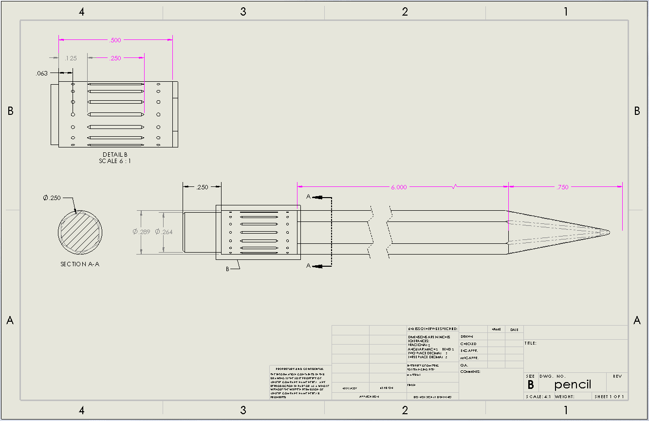
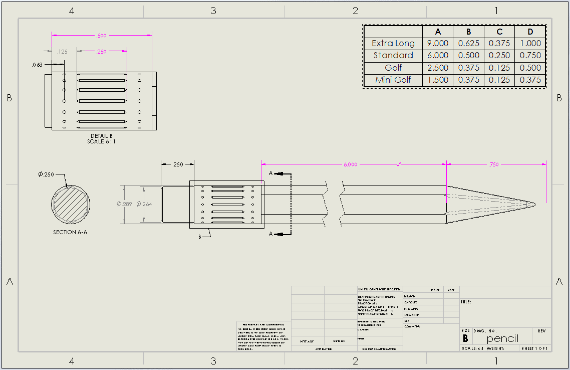
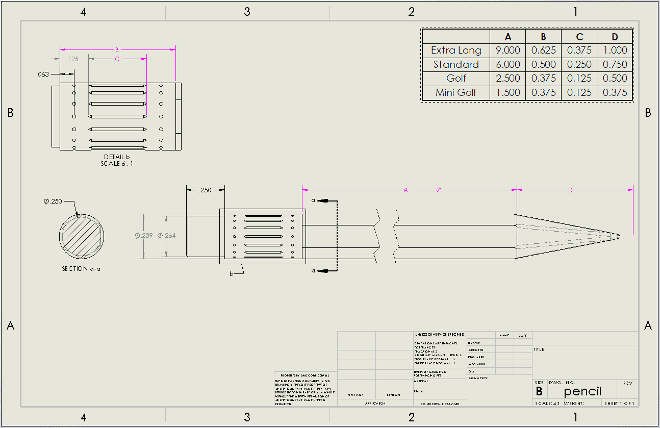
Once the part is ready, I can start the drawing. The key aspects of the design can be illustrated fully using just a Top view, a section view through the hexagonal body, and a detail view of the ferrule. Since I will use the design table to explain the differences between the four configurations, I only need to show one configuration in the drawing views.
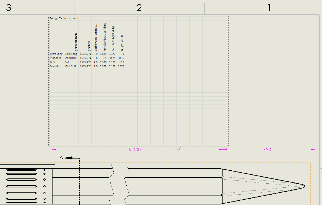
Model Items and Smart Dimensions help me gather up the critical part dimensions. The dimensions controlled by the design table appear in hot pink by default. (This color is defined in System Options > Colors under “Dimensions, Controlled by Design Table.”) The remaining dimensions on the sheet are the same for each configuration, so I won’t have to worry about these values being ambiguous.
At this point, my drawing is ready for the design table. To insert it, I need to select a drawing view and then find Tables > Design Table from the CommandManager. (The Design Table option will not appear unless a view is preselected.)
However, as you can see below, the result is not particularly pleasing to look at. There are tons of empty cells, and I have no ability to crop these out in the drawing. In fact, there is not much that can be done to the table in this drawing, which highlights an important concept: The design table will appear in the drawing exactly the same as it appears in the model. In other words, any desired changes to the table—including fonts, hidden rows or columns, numerical precision, and more—need to be made by editing the design table in the model’s ConfigurationManager.
Since the default display of the design table in the drawing can be large and unwieldy, I would suggest making your formatting adjustments before you even try to insert it. Mine is already on the drawing though, so once I get things cleaned up at the part level I’ll just push those changes to the drawing.
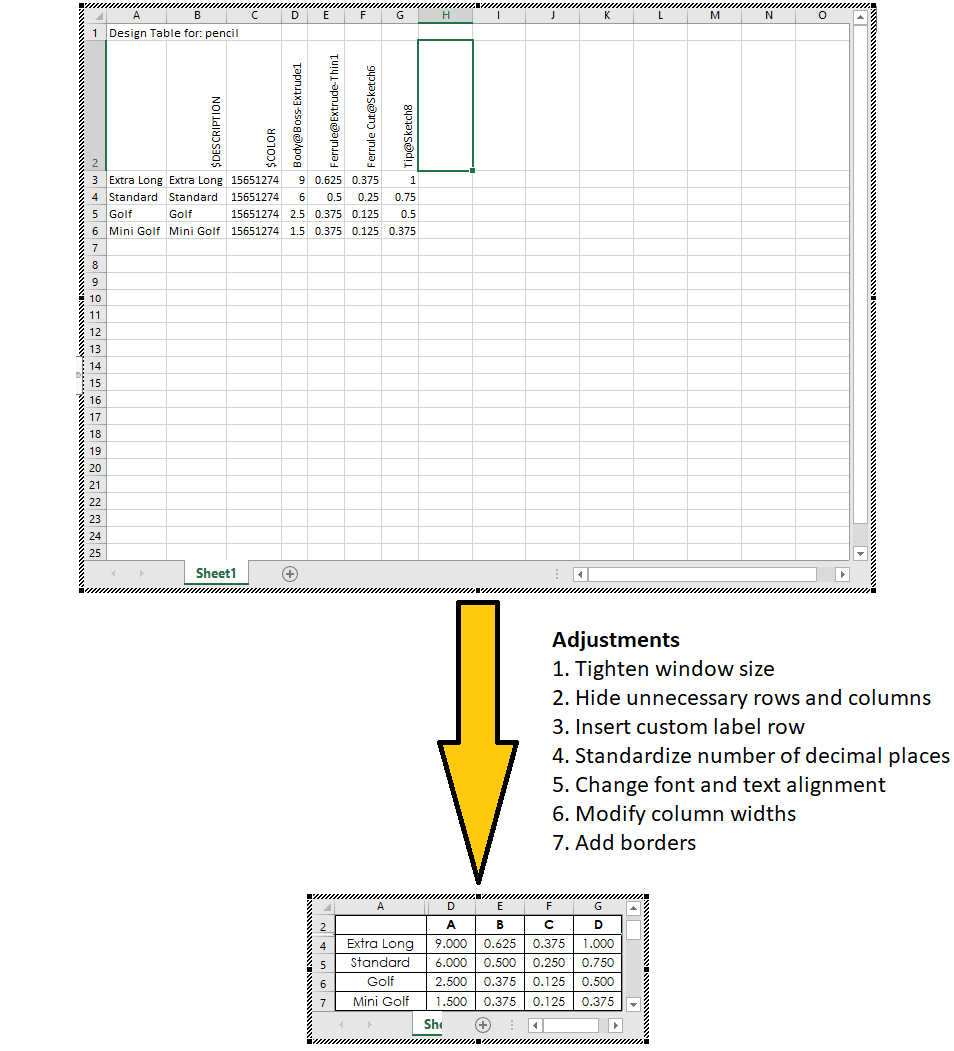
In the part, launching the design table with Edit Table previews what is seen in the drawing. To eliminate empty rows and columns, I can drag the borders of the window inwards. I don’t need the $DESCRIPTION and $COLOR columns or the title row to appear in the drawing either, so I can right-click Columns B and C and Row 1 and select Hide to get rid of them, just like in a normal Excel spreadsheet.
Instead of using the default “Dimension@Feature” format in the drawing, I want to just assign a letter to each dimension. I can add a new row above the current dimension row, enter my custom labels there, and then hide the original dimension row.
My dimensions currently have anywhere between zero and three decimal places. To ensure uniformity, I need to adjust the Number Format settings from the Excel banner. This involves selecting all the cells with numeric values, setting their format to “Number,” and using the Increase Decimal option until I get to three places.
All that is left now are some adjustments to make the table easier to read. All cells should use Century Gothic to match the rest of the drawing (with bold typeface for the symbol row), and the text should be centered within each cell. Column A has the configuration names, so it needs more space than the rest of the entries; the Column Width tool allows me to control the horizontal span of each column. So the table will stand out, I want it to be bounded with thick borders and have standard lines running between each cell. (I found it easiest to use the More Borders option to set this up manually instead of using one of the preset border selections.)
The Custom Views tool in Excel can be used to create and switch between different snapshots of the table. A custom view saves certain characteristics of the table display, such as the visibility of columns and rows. Adding a view once everything is formatted to your liking can make the table easier to work with. If you need to temporarily unhide certain cells to make changes to the model, you’ll be able to quickly reactivate the saved view when you’re done to ensure the drawing regenerates correctly.
Since I already inserted the table into the drawing, I just need a forced rebuild (Ctrl-Q) to get the document to update with these modifications. The table now fits more easily onto the sheet, allowing me to reposition and resize as needed.
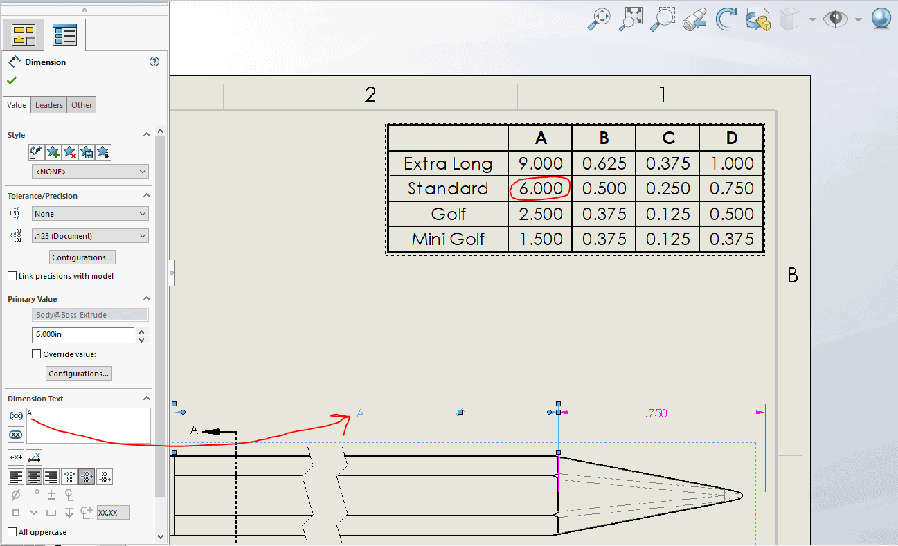
The final step is to match the dimensions on the sheet with their label in the table. For each pink dimension, I want to delete the default “<DIM>” in the Dimension Text field of the PropertyManager and override it with the corresponding letter from the table. I just need to look at my Standard row in the table to figure out which dimension is which.
(To avoid confusion between the section and detail names and the dimension labels, I’ve renamed these views to use lower-case letters—Section A-A has become Section a-a, and Detail B is now Detail b.)
With this design table, I have essentially created a tabulated drawing, clearly and fully describing all members of the part family in a single document. I hope these instructions have been helpful. If you often work with design tables in parts or assemblies but haven’t yet applied them to a drawing, try it the next time you need to detail a model. I think you’ll find it to be a both quick and powerful technique.
(ADDENDUM: Here are a couple other suggestions I wanted to include for working with design tables that I couldn’t really fit in with the steps above. If you want to open the design table while you are in the drawing, double-clicking the table will bring you to your model and launch the table within the SOLIDWORKS window. Again, if you make any changes to the design table, do a forced rebuild after switching back to the drawing to ensure the table there is current. Similarly, if you make a change to a controlled dimension while the design table is closed, you should reopen it to update any affected cells.)
Anthony Sandri
Application Engineer
Computer Aided Technology, Inc.