SOLIDWORKS: How to Use Design Tables for Assemblies
Utilizing Design Tables is very handy and certainly saves time with designing as well as modifying. While using Design Tables to assist with the creation of multiple Configurations at the Part Level is common, what about at the Assembly Level? Currently, the same technique doesn’t apply but there is a way in which we can still accomplish this task.
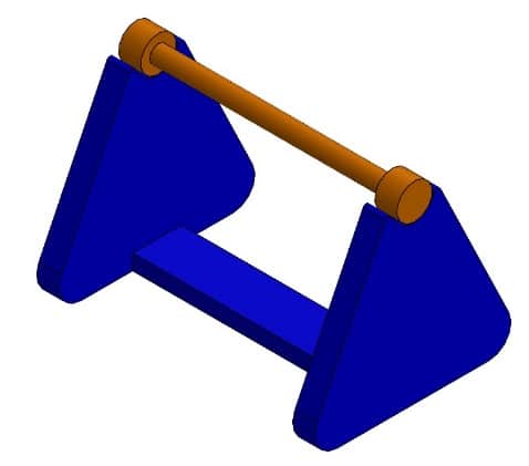
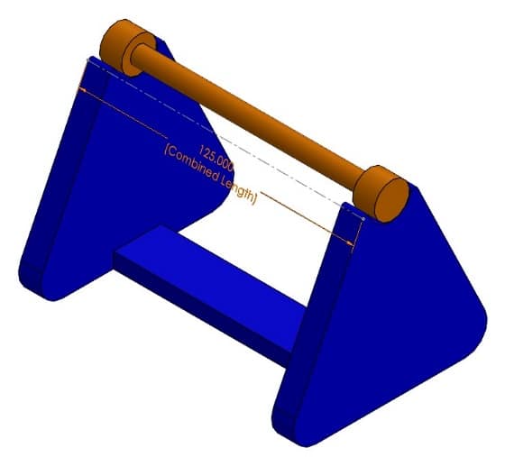
Here is a simple Assembly in which we intend for a Design Table to create a few additional Configurations. In each Configuration, the length of the blue Frame and the orange Rod will change in tandem.
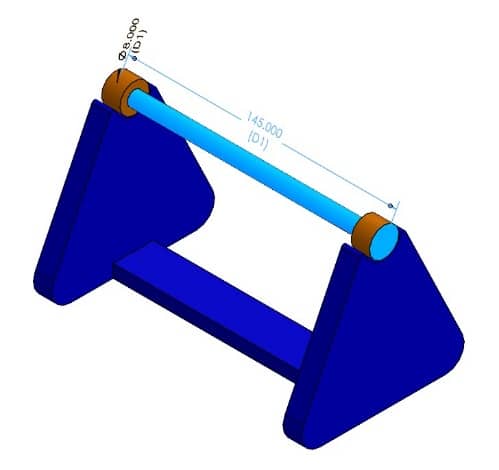
For the sake of Design Tables, it is very helpful to name the dimensions we intend to use. The Dimension names can be displayed in the graphics area by toggling on the ‘D1’ icon under the ‘Hide All Types’ eyeball icon within the Heads-Up Display Menu or by selecting View>Dimension Names. It is also advantageous to right click the Annotations Folder from the Feature Manager Design Tree to turn on both ‘Show Feature Dimensions’ and ‘Display Annotations’.
As Part dimensions are only meant to be majorly changed at the part level, there is a way to allow for these changes within an Assembly environment. With the creation of an in-context sketch, we can relate its dimension to each dimension we intend to modify by using Equations.
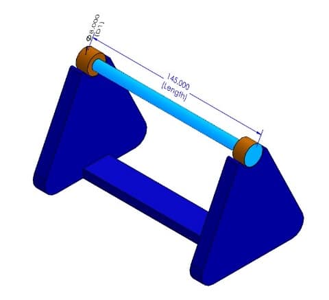
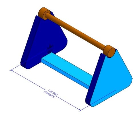
For our example, we’re using the side face of the blue Frame for a new ‘in-context’ sketch in the assembly. As only the length of both components are changing, we use a simple construction line with only one coincident relation at the fixed end of the pipe. The second vertex of this construction line is left under-defined and the line is only horizontal with the edge of the frame to allow for dimension updates.
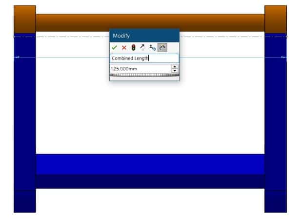
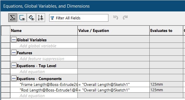
We start the dimensioning process by applying a dimension to the new sketch. This will be arbitrary initially. Now we modify the length dimension of the frame to set it equal to the new sketch. This can be done by double-clicking the dimension to bring up the on screen Modify window. Enter an equal sign in place of the value and then select the sketch dimension. The two dimensions are now set equal to one another. Next we do the same to the rod dimension; setting it equal to the same sketch dimension. This allows for both Parts to update together with one dimension change. More complicated equations can be applied to allow for variable changes in relation to one another. We’ll keep this example simple.
We can then select ‘Insert>Tables>Design Table’ from the drop-down menu. In the property manager of the Design Table, you can choose to create a blank DT and then manually insert the desired parameter; or several for other circumstances. Having changed the Dimension Names, this makes it easier to identify what is what.
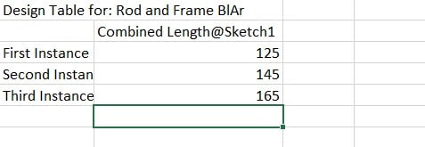
Finally, you can add additional Instances or Configurations that will have respective updates at the Assembly Level.
For more information related to Part Level Design Tables, check out this link:
https://www.cati.com/blog/2018/06/create-manual-configurations-design-tables-solidworks/
Gabriel Rodriguez
Application Engineer
Computer Aided Technology, Inc.