SOLIDWORKS: Creating GD&T it's easy
What is SOLIDWORKS Geometric Dimensioning and Tolerancing (GD&T)?
GD&T is the process of assigning dimensions and tolerances to features of a part in a way that makes it possible to manufacture, inspect, and assemble. It is used to add geometric tolerances using feature control frames to parts and drawings. SolidWorks drawing’s geometric tolerancing tools support the ASME Y14.5-2009 tolerancing guidelines.
Back in the day when I was using AutoCAD, we were required to add GD&T to our drawings. GD&T was my favorite. I absolutely loved creating GD&T, NOT. When using AutoCad, we would create blocks to represent GD&T. That made it easier but was still a pain.
With SOLIDWORKS GD&T, it is easy and actually fun. Let’s take a look.
Like I mentioned above, you can add GD&T to part files. Look at this blog from my co-worker Ryan Field. SOLIDWORKS MBD: The next step in the evolution of part definition.
I will show you how easy it is to create GD&T in a drawing.
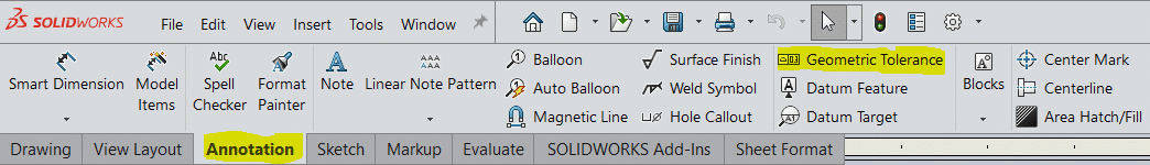
From your Annotation Command Manager Tab, click Geometric Tolerance.
This dialog box pops up and will allow you to select what symbol you want to add, as well as other tolerance or dimensions. You can enter numeric or alpha values.
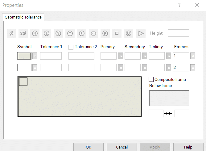
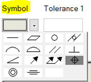
You will want to start by selecting a few Symbol.

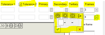
Then add your tolerance’s. You can add Tolerance 1 and/or 2. You can also add Primary, Secondary or Tertiary values, they have pulldowns with a combination of type-in and symbol buttons.
If you need more frames, click the down arrow.
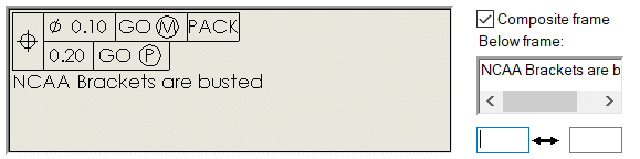
If your initial symbol is the same, you can merge them by clicking the composite frame check box. If needed, add notes to the bottom of the frame.
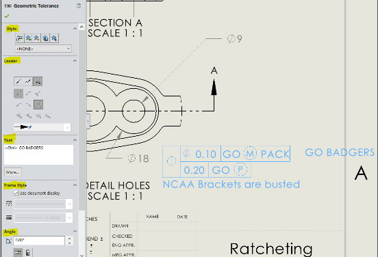
Once you have entered your symbols and values, single click on the sheet to place the GD&T and then click ok. You can add multiple GD&T’s with multiple single clicks. You have options in the property manager to change/add Styles, leaders, text, frame style and more.
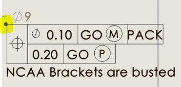
Another cool part is you can attach the GD&T to other dimensions by left mouse click and hold, then drag and release on dimension, it will move with the dimensions. If you want to detach, click dim to highlight. Left mouse click and hold on blue dot and drag off.
I almost forgot to mention. If you double click the GD&T, you can edit it. If you click to select the GD&T, you can also copy and paste.
Applying SolidWorks GD&T standards can cut down on the time it takes to create a drawing or part. A fully detailed drawing or part with proper GD&T can be done in a fraction of the time that it would have taken without it.
I hope you found this helpful! Thanks for reading.
Roger Ruffin
Sr. Application Engineer
Computer Aided Technology, Inc.