Slow Your Roll, Slow Rotating Regions in SOLIDWORKS Flow Simulation.
If you have used SOLIDWORKS Flow Simulation, you will likely know that one of the best enhancements in recent years is the “Sliding Mesh” rotating region feature. This boundary condition is geared towards turbo machinery design, allowing the impeller/ rotating geometry to drive fluid flow. This technology is an advanced option for designing impellers, volutes, propellers or anything else you want to rotate in a fluid. As you might have noticed these applications rotate at a fast rate usually 100’s or 1000’s of rotations per minute. In this blog we are going to slow things down and use this technology to replicate rotating a ball valve.
![]()
Typically, when solving for different states of closure in a device like a ball valve we would use configurations and steady state solutions to understand things like pressure drop, velocity, etc. at different valve angles. These steady state analyses run quickly and provide definitive answers to the engineer fast.
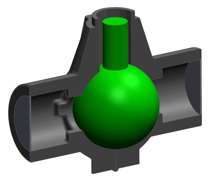
Assigning a rotating region that is sliding, specifically needs an additional body or part to define what is sliding in the model. Here you see the ball valve geometry in gray, and the sliding rotating region in green.
![]()
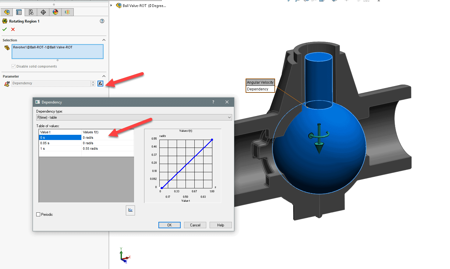
Assigning this sliding region allows us to define the rotational rate and the time the rotation takes place within. I used 0.55 radian rotation over a span of 1 second. This rotates the ball valve roughly 30 degrees from fully open.
I used a dependency with time to allow the flow to fully develop before the ball rotates. This dependency is located at the function button in the rotating region definition.
I used a default time step for this analysis as the rotation is very slow relative to the flow rate, but when defining a fast rotation, it is a good idea to use a small-time step to capture 10 increments between one position of the rotating device to another.
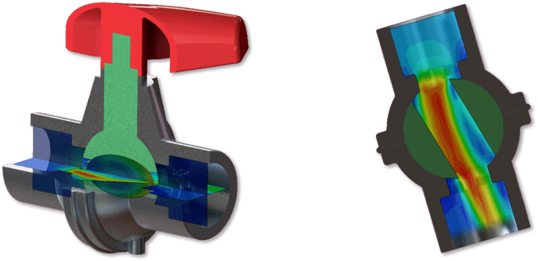
The results are impressive and give a live view of the valve closing and its affect on the water flow through the system.
Utilizing SOLIDWORKS Flow Simulation to gain insight into your design is invaluable. Flow gives real engineering answers to its users enabling them to make better decisions throughout their design process. If you want to learn more about SOLIDWORKS Flow Simulation and SOLIDWORKS please reach out to CATI.
Robert Warren
Simulation Specialist, Elite Application Engineer
Computer Aided Technology, Inc.