Mesh Controls in SOLIDWORKS: Not just for Faces and Edges
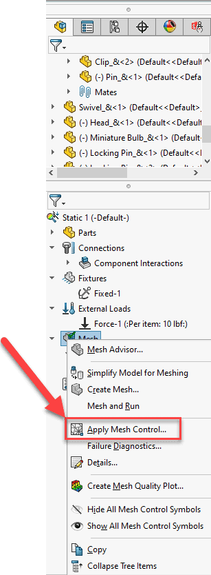
When it comes to mesh controls, people often ask if they can be applied to an entire part instead of to edges, faces and vertices. The answer is of course “Yes”, but the method is slightly different than it is for edges, faces, and vertices. Outside of the mesh failure diagnostic window, there are two workflows/methods for applying mesh controls to parts and one of them is a little less obvious than the other. Let’s dive in and start with the more obvious of the two. This method will have us start by RMB (right mouse button) click on “Mesh” in the Simulation Tree.
A menu will pop up and there will be an option for “Apply Mesh Control”.
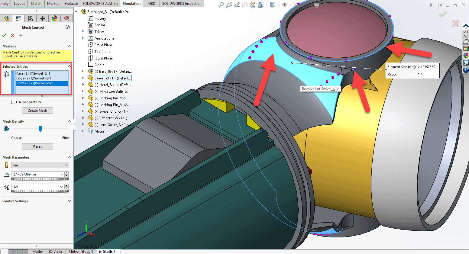
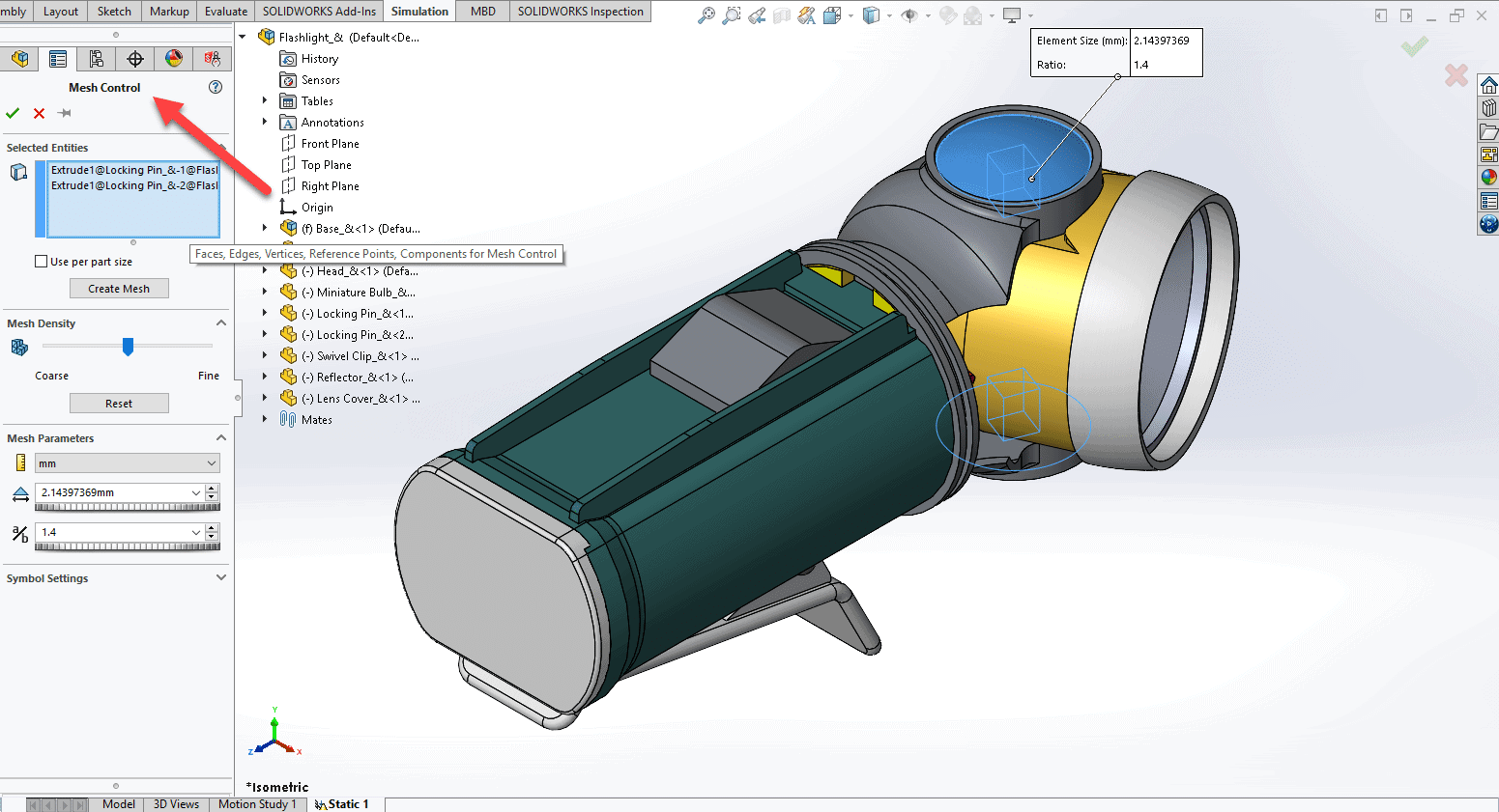
Now the Mesh Control property manager opens on the left side of the screen. If you hover your mouse pointer in the blue area under “Selected Entities”, it will say “Faces, Edges, Vertices, Reference Points, Components for Mesh Control”. If you try and select a component/part from the graphics window, it will only select faces, edges, or vertices.
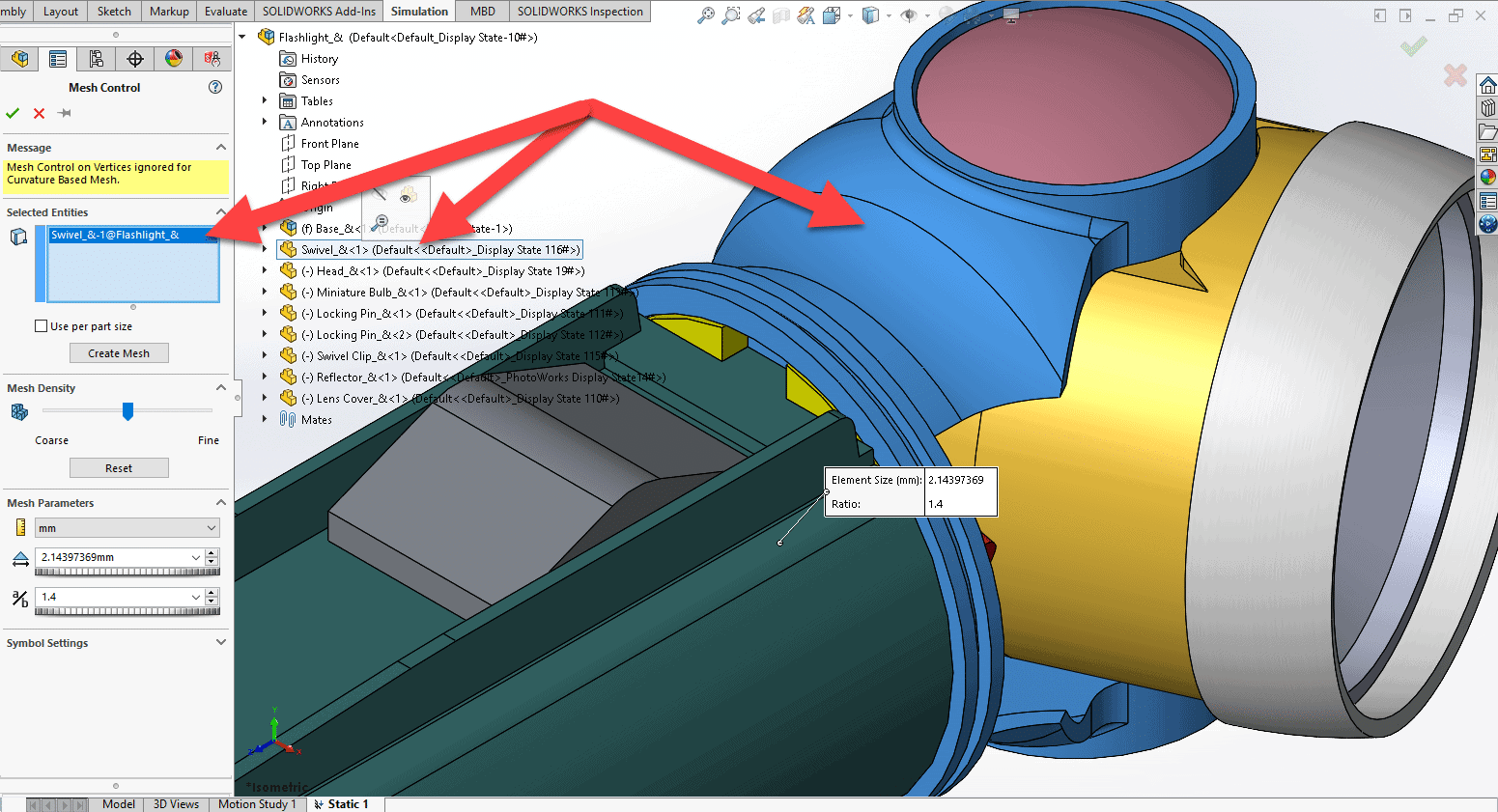
So you may be asking yourself, “How do I select a component/part?”. You select a component/part by clicking on the part from the FeatureManager Design Tree that is floating to the right of the Property Manager.
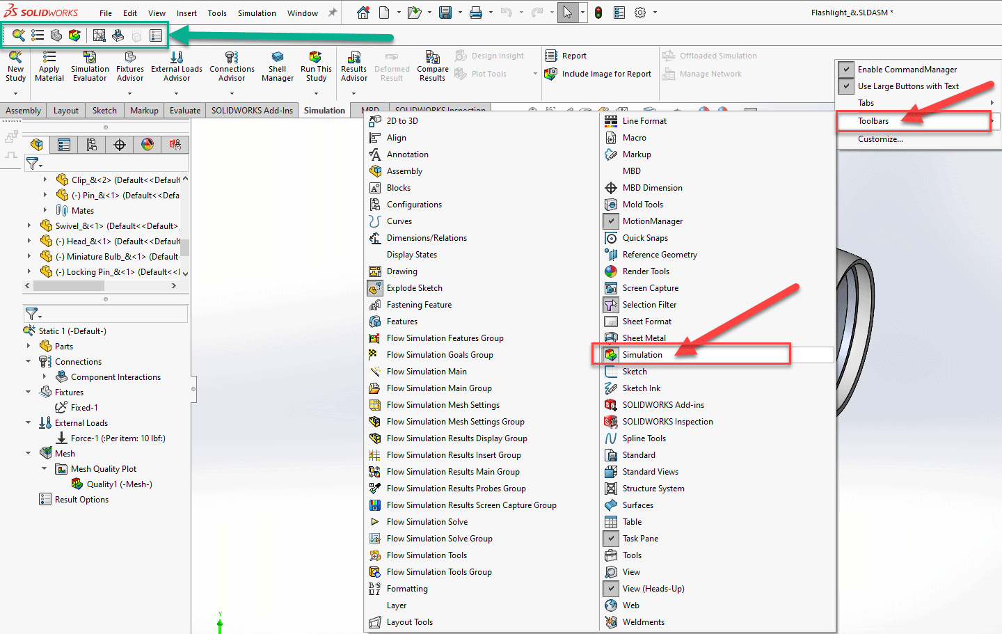
That is our first method for selecting components/parts that we want to apply mesh controls. This method can also be activated by selecting the Mesh Controls command from the Simulation toolbar if you have it active. In the image below, it shows the Simulation toolbar inside the green rectangle, and it shows where the toolbar can be activated in red.
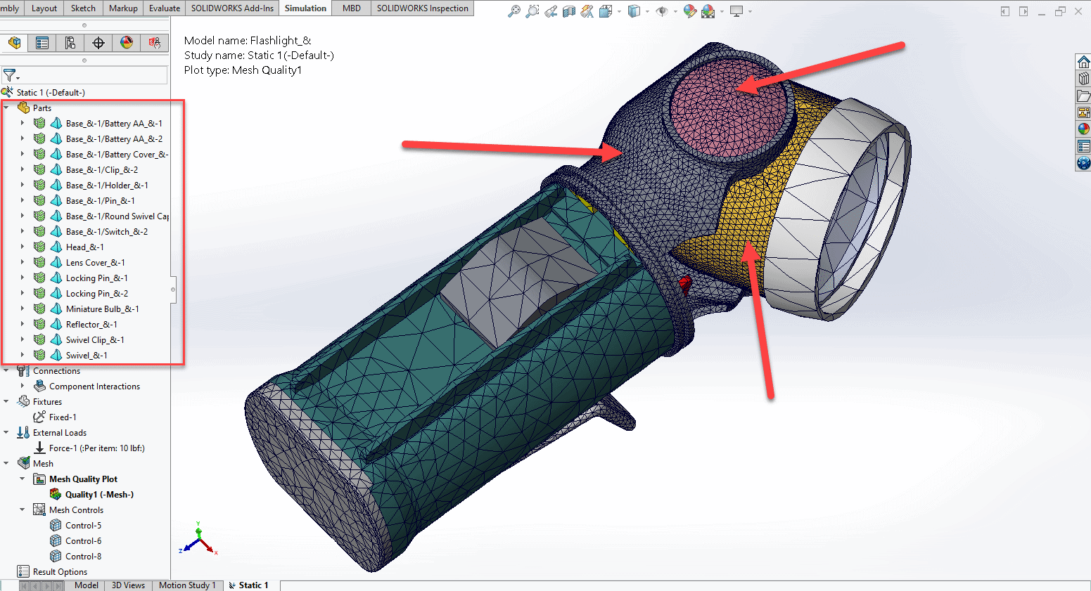
Now let us look at the 2nd method for activating the Mesh Control command. This workflow will be slightly less obvious. If you click the dropdown arrow next to “Parts” in the Simulation Tree and then RMB on one of the parts, you will get a pop up menu. This one looks a little different than our previous pop up. In this one we see an option for “Create Mesh”.
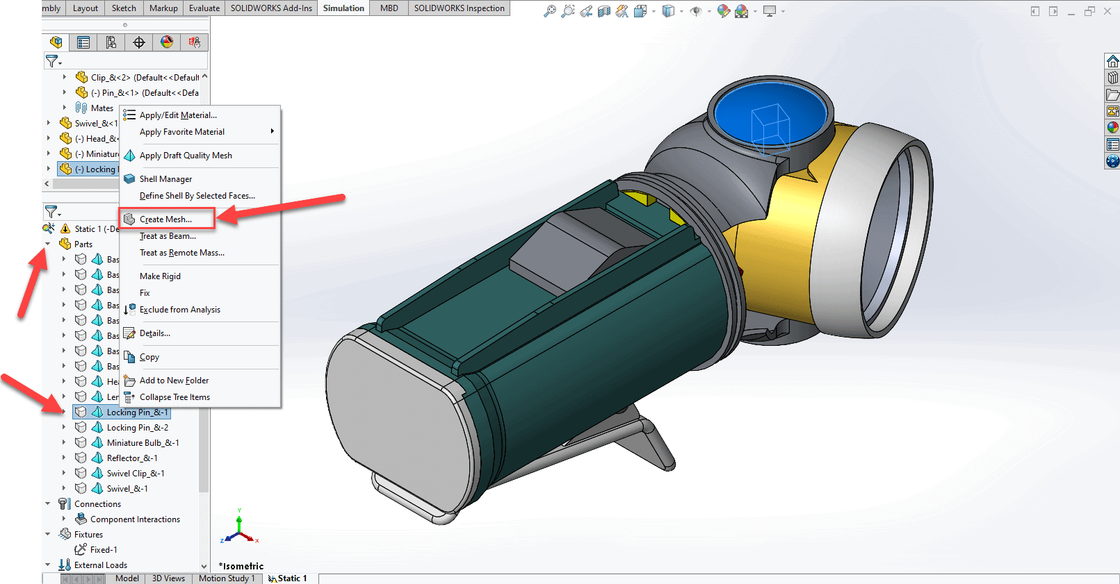
I say that it is less obvious because the command is labelled “Create Mesh”. “Create Mesh” is generally what we use for the global mesh settings, not mesh controls. It will be surprising for many of you to know that if you select the “Create Mesh” command from this menu it will in fact activate the “Mesh Control” command. See below.
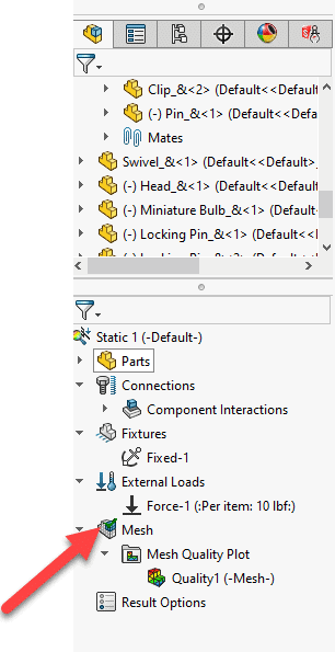
This can be a very helpful workflow if we have a part that fails to mesh like we see in the image below. See the part with the red mesh icon next to it.
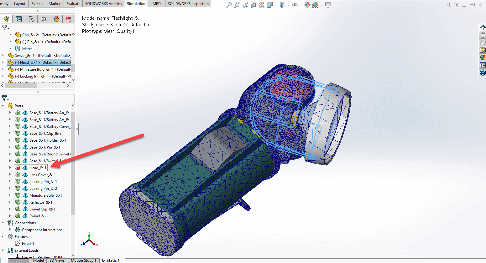
This is a perfect candidate to apply a mesh control directly from the Simulation Tree.
Once we have applied our final mesh control and meshed the model we can see that our meshing issues have been resolved.
Do keep in mind that by using this method you will be increasing the length of the solve time since you have increased the number of tetrahedrons. One last tip, these methods can also be used for Multi-body parts. I hope you all found this blog helpful!
James Reeher
Application Engineer
Computer Aided Technology, Inc.