SOLIDWORKS Electrical: How to Flip the Horizontal Terminal Strip Drawing
When inserting terminal strip symbols in the schematic, the red arrow designates which side is pin 1. In the final terminal strip drawing that gets produced, if you have it draw vertically, pin 1 ends up on the left; if drawing horizontally it is on the bottom. That means for horizontal strip drawings, the red arrow indicates the load/field side, while for vertical strip drawings it indicates the opposite. How can we change that so the red arrow still indicates the same thing for horizontal terminal strips? We want pin 1 on the top.
There is no single setting we can adjust to flip the terminal strip drawing, unfortunately, but I have figured out what to change to get it ALMOST perfect.
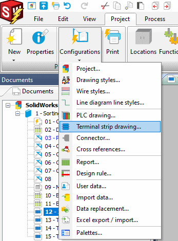
Go to Project > Configurations > Terminal Strip drawing…
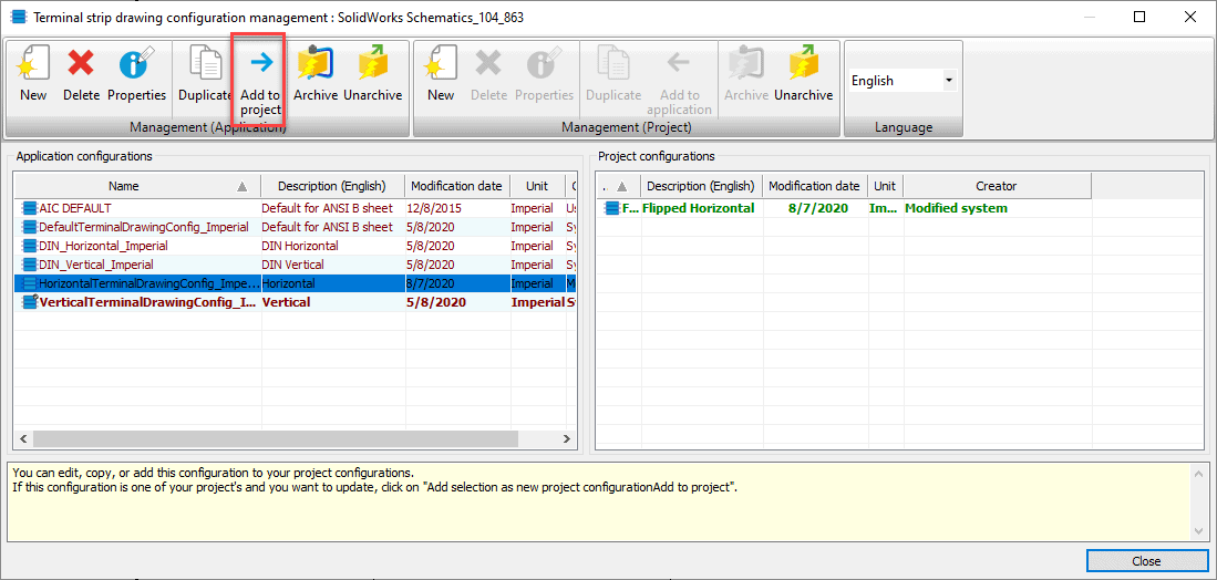
Add the horizontal configuration to the project level. That way you can just delete it if you don’t like the end result, without having messed up the original settings. Then change the name and description to Flipped Horizontal.
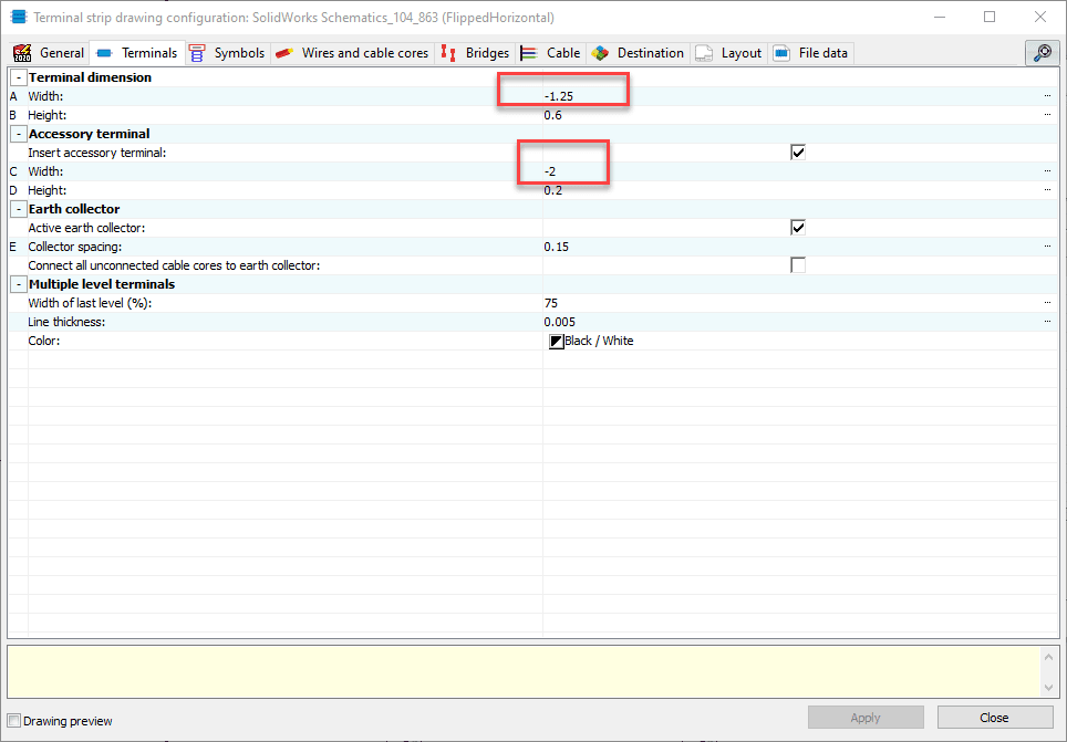
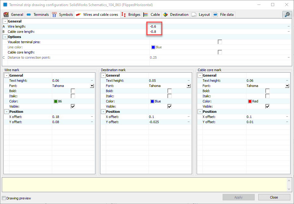
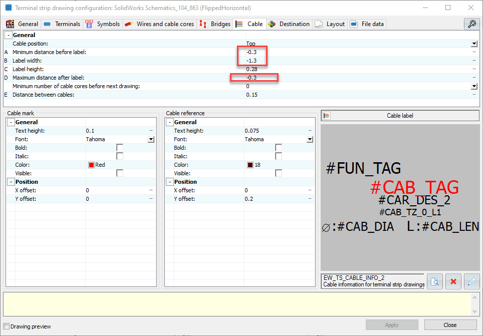
Modify the newly created project level configuration, changing the numbers highlighted in the following pictures to be negative instead of positive numbers.
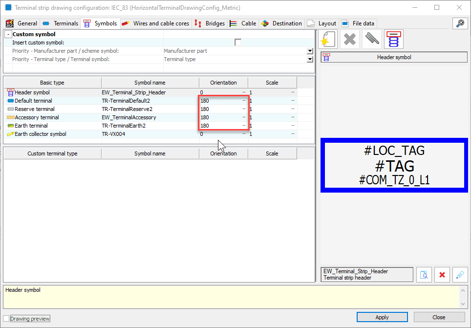
On the symbols tab, change the orientation of the symbols to 180. This is possible in 2021 or newer. In 2020 or older, you won’t be able to do this, and although the drawing will flip all the connections properly, you won’t be able to display the terminal connection numbers properly as they won’t rotate to be on the correct sides. You can either have your terminals not have terminal marks, you can remove the attributes from the symbol it is inserting to label the terminal, or you can move the attributes in the symbol so that the attribute for pin 1 is next to pin 0, and the attribute for pin 0 is next to pin 1.
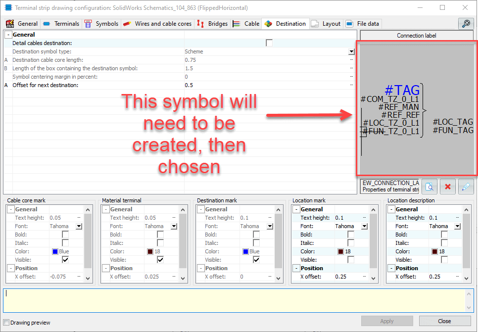
Finally, on the destination tab of the configuration window, you’ll have to pick a different symbol to populate the destination information for cables. I had to go to my library and copy/paste the original symbol, then edit the pasted symbol to be mirrored. After creating the new symbol, you can select it in the configuration window.
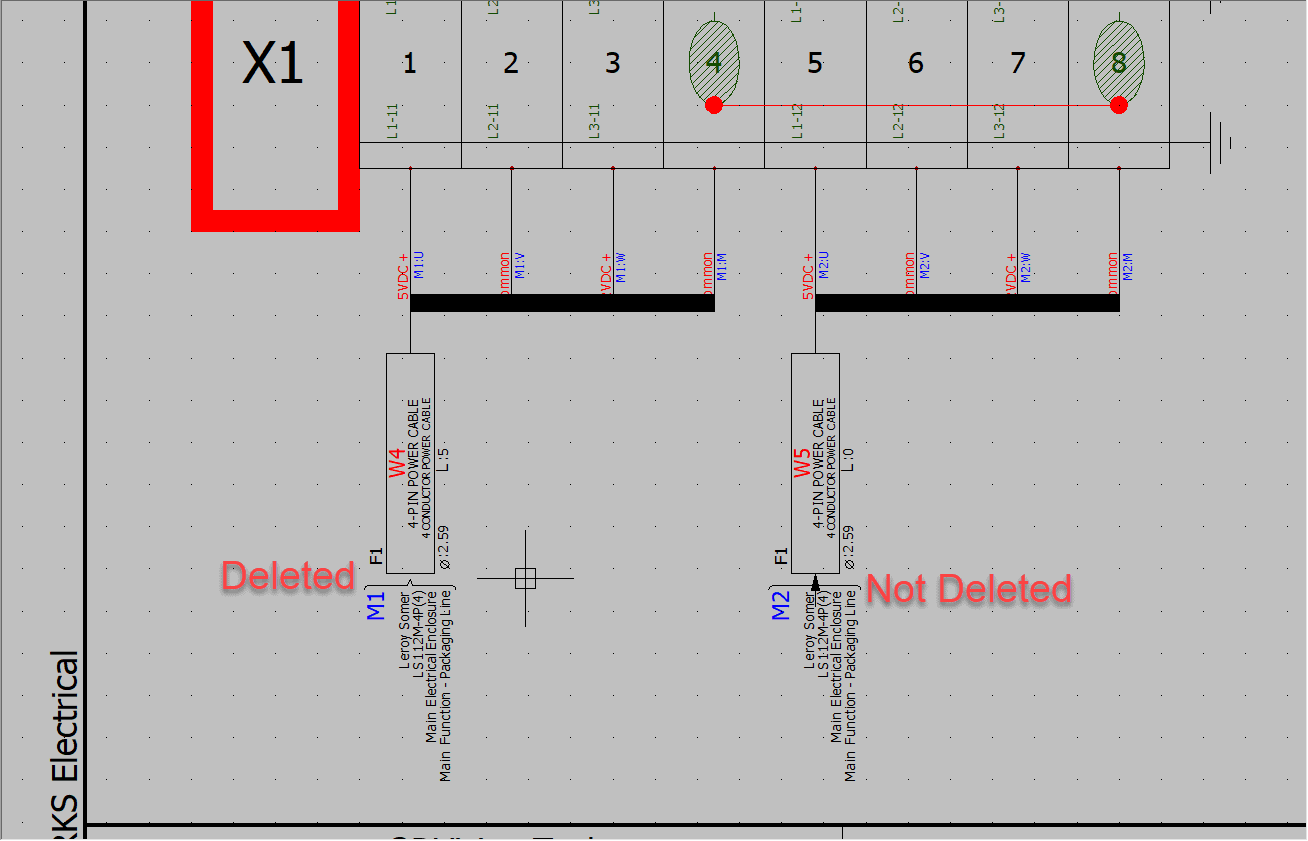
When all of that is done, you can generate the horizontal terminal strip drawing, and the load/field wiring will be on the bottom instead of the top. The one thing I couldn’t get fixed, is the little arrow that gets drawn between the cable label and the cable destination information. You can leave it alone, or delete the arrows. If you delete them, then just know that any updates to the drawing will re-draw them.
Hopefully that gets you going with your terminal strip drawing. SOLIDWORKS does listen to feedback so if you still can’t quite get it right, check to see if there are any enhancement requests you can vote on at the customer portal.
Brian Cooke
Sr. Application Engineer Specialist, Electrical
Computer Aided Technology, Inc.