Troubleshooting Methods for Import Diagnostic Failures
We’ve all been there before. You receive a neutral file from a customer and – upon opening it – several surfaces have failed to translate. No worries, you say, I can use the Import Diagnostics tool. You run Import Diagnostics, but there are still several surfaces or gaps that fail to be healed by the automatic patching tool. Now, you’re stuck!
Some designers avoid this situation at all costs. They are parametric design modelers, not surfacing experts. They want practical surfacing knowledge, not a second degree in it. If any of this describes you, keep reading.
In this article, you’ll learn the best file types to use in SOLIDWORKS before learning some commands and instructions for addressing these failures. Now, this isn’t a one-size-fits-all troubleshooting method. Sometimes, there isn’t anything you can do but ask for a different file type, or spend hours patching surfaces.
Understanding Why
The main software component responsible for generating 3D model graphics is called a geometric modelling kernel. The most dominant modelling kernels go by names you may be familiar with, called Parasolid and ACIS. Less common kernels are usually proprietary. SOLIDWORKS, however, runs through Parasolid – which is part of the reason for it’s market dominance.
Have you ever tried to translate an English sentence into another language on Google Translate, then converted it back to English? It doesn’t always come out the same, does it? Well, the same is true with modelling kernels. Because we do not live in a vast open-source world where everyone speaks the same language, translators aren’t perfect. This is why models end up missing surfaces after opening.
Best Neutral File Formats for SOLIDWORKS
Because SOLIDWORKS’ geometric modelling kernel is Parasolid, file formats in this file type will give you some of the best results. Their file extensions will be either .x_t or .x_b. The differences between the two indicate Parasolid text files (denoted by “t”), and Parasolid binary files. Binary files are smaller but have less support through various applications. Request a Parasolid file for use in your SOLIDWORKS environment if possible.
A great second choice is the use of a STEP file. STEP is an acronym for Standard for the Exchange of Product Data, which was developed as an ISO standard exchange format. A STEP file is not a modeling kernel. It is a file format. Since this was developed as a standard addressing this exact issue, generally users see more success with STEPs.
Surfacing Techniques
When encountering neutral files with failed import diagnostic faces or gaps, the best thing to do is reduce the number of failed faces in any way possible. For parts with symmetry, the first technique is the Cut with Surface command. The idea here is to get rid of one side of the part with more failures so there is only half of the part to work with. This should help cut down on how many surfaces that need patching. Once patched, simply mirroring the body will allow the body to form its full, watertight solid body.
The most known surfacing tool for failed surface imports is the Filled Surface command. The filled surface command is one of the most common tools for this task. After exiting import diagnostics, select Fill Surface. Under “Patch boundary”, select the edges that form the border of the missing geometry. Most of the other stuff in the PropertyManager is not so relevant, but the curvature control helps define the overall surface shape. More on filled surface.
There are three types of curvature control: Contact, Tangent, and Curvature. If you specify an edge to have “contact”, there are no smooth tangencies considered, and a sharp corner is formed on that edge. If you specify tangent control, it will create a surface that maintains tangency of the patch edges. For even smoother transition between faces, use “curvature” to match surface curvature of the selected surface. Use contact for sharp angles and curvature for smooth transitions as a general rule of thumb.
If you’re unsure of which to use, explore the outputs of each surface by changing the curvature control of one or more edges at a time.
Most surface failures are caused by fillets. Filleting is a type of “non-analytical geometry”, which does not rely on equations to exist in a model. Another technique for getting rid of these pesky surface problems is by using Delete Face command. This is one of my favorite methods to use because it’s remarkably simple, and slightly counter-intuitive. By using Delete Face’s “Delete and Fill” command on models with incomplete fillet geometry, whole surfaces can be formed in an effective way.
The first trick here is to try to understand how the missing surface fits in with the rest of the geometry. Maybe the missing face was part of a fillet, or another curve. Then, using Delete and Fill, select the surface that might belong to the same feature of the missing surface for deletion.
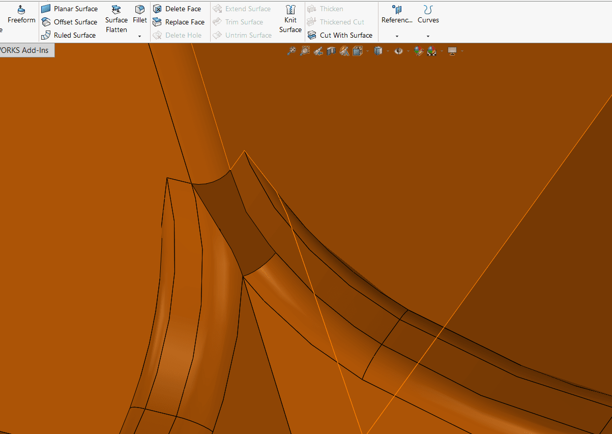
Let’s take a look at this in the missing surface below.
Of the four edges, which face should we select for the “Delete and Fill” command?
We should try to delete and fill the one that corroborates with the same fillet edge. The image below shows what I mean by this. The green arrows follow those faces upward toward the edge to give visualization for what I’m looking for. The numbers symbolize the order in which I might try to delete and fill my surfaces.
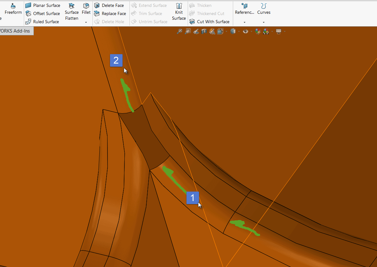
Results vary, but this is a great way to patch faces with more complex curvature. It is simple to use — yet unique — since we’re adding material by deleting material.
Fillets can cause several complications for translations, and if your model is still not the way it should be after following these troubleshooting techniques, here’s a few more Hail Mary tips:
1. Consider asking for files with fillets removed (if your application allows). Then apply the fillets yourself.
2. Try saving the file as a different file type of neutral format before re-running import diagnostics.
Summary
If you’ve found other techniques that have worked for you that weren’t mentioned, be sure to mention it in the comments or by checking out my LinkedIn page and sending me a direct message. I’d love your input!
SOLIDWORKS modelling kernel, Parasolid, is a common but proprietary language. For this reason, translations throughout the multitudes of CAD environments are less-than-perfect. If you can help it, encourage file output in Parasolid or STEP. If import diagnostics still doesn’t work, using Surface Fill or Delete and Fill through the Delete Face command can help patch missing geometry without the need for extensive surfacing knowledge. Using “Cut with Plane” on symmetric parts can reduce the amount of failed surfaces.
I hope this method saves you as much time as it did me, and until next time…
Happy Designing!
Jordan Kleinschmidt, CSWE
Applications Engineer
Computer Aided Technology, Inc.