3D Hydraulic Jump in SOLIDWORKS Flow Simulation
In my previous blog, I showed an application of the free surface feature in SOLIDWORKS Flow Simulation. For a 2D section of a spillway and flow over a weir, I showed how this feature can accurately predict the hydraulic jump. Well, 2D isn’t that exciting, is it? That’s why we love to use SOLIDWORKS in the first place! So I generated a 3D simulation and found impressive looking results while learning some new things along the way.
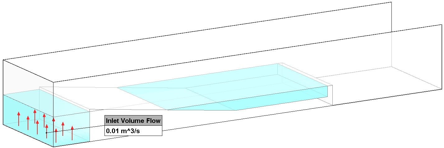
Here’s the model before the 3D solution. It depicts the spillway and standing pools of water (in light blue color) with a flow condition applied to the lower face of the upstream supply pool.
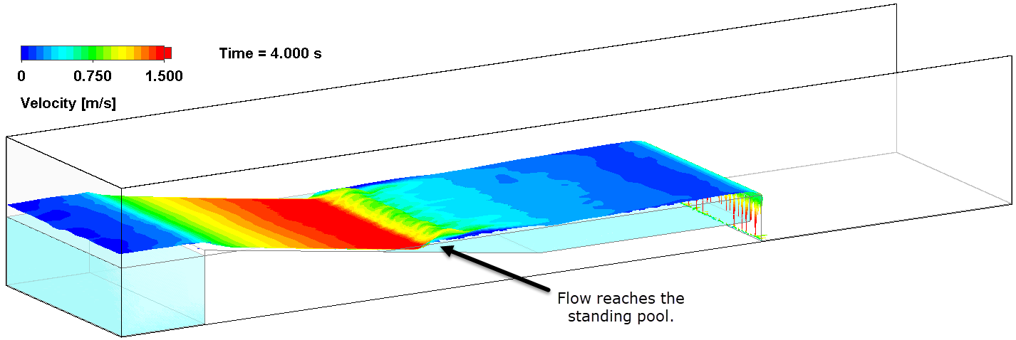
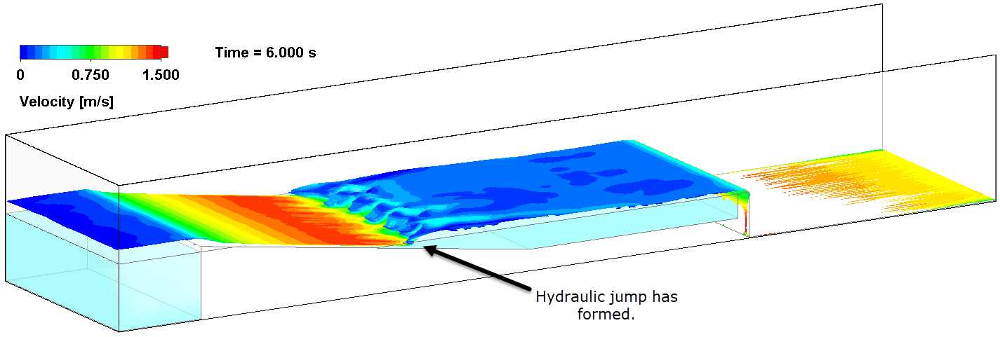
The transient simulation was solved for a total time of 10 seconds, resulting in formation of the hydraulic jump starting at about the 5-second mark.
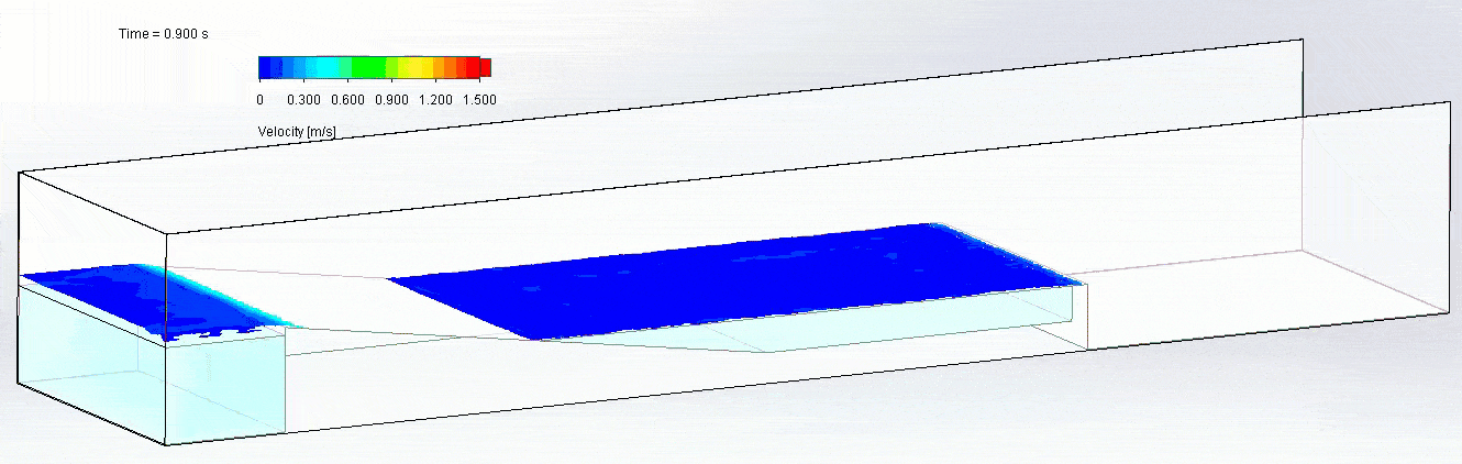
The following isosurface plots taken at 2, 4, and 6 seconds show the free surface colored with flow velocity. Note the high flow velocity on the spillway ramp and very low velocity on each of the pool surfaces. 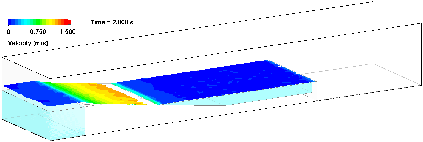
After it formed, the hydraulic jump remained stationary for the remainder of the 10-second simulation. In a side view, a plot of the volume fraction of water with an overlay of the streamlines shows the jump and areas of re-circulation in the air and water caused by turbulence.
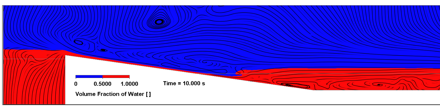
I mentioned learning some things about this functionality along the way. One is that the free surface is best captured by a volume fraction plot, as opposed to a mass fraction plot. The significantly greater density of water causes the mass fraction plot to show a value close to 1 even in regions with very small water volume.
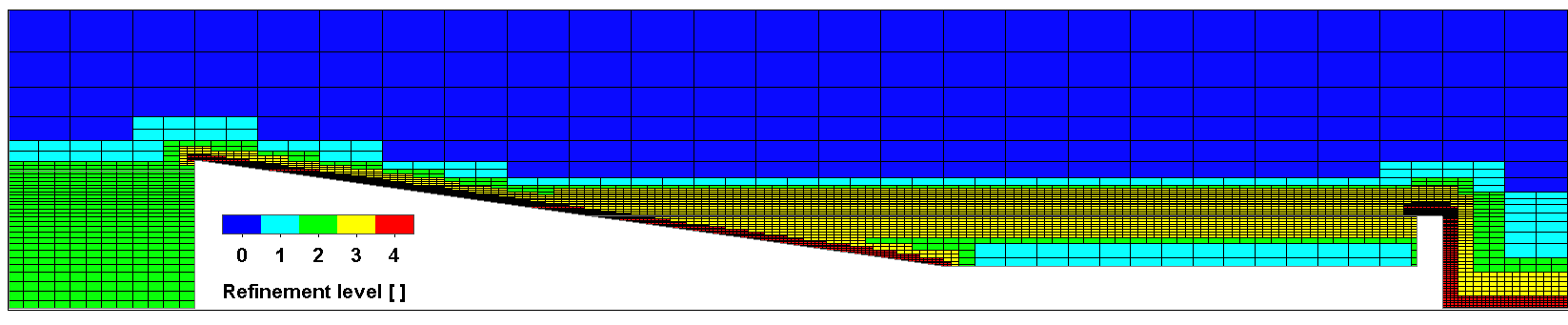
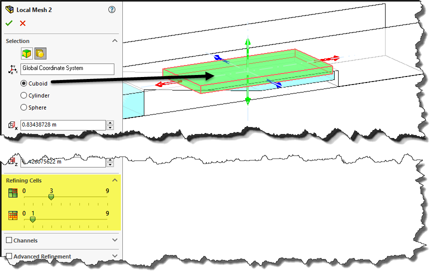
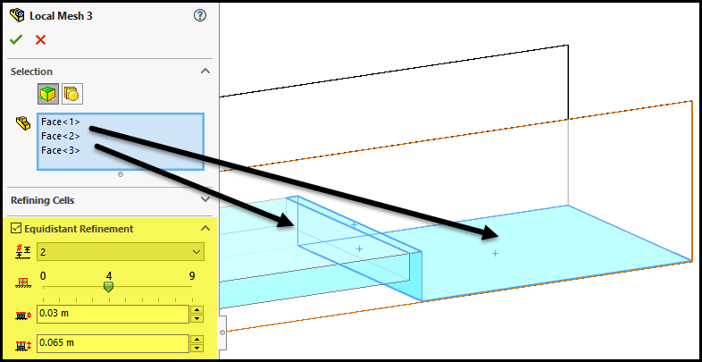
Secondly, in order to accurately capture the hydraulic jump in 2D or 3D, the mesh must be significantly refined wherever the free surface will form, so it takes some planning and trial runs to come up with an adequate mesh. The cut plot below shows that I’ve generated a mesh with a maximum refinement level of 4 (red-colored cells). I used 3 local mesh controls to accomplish this.
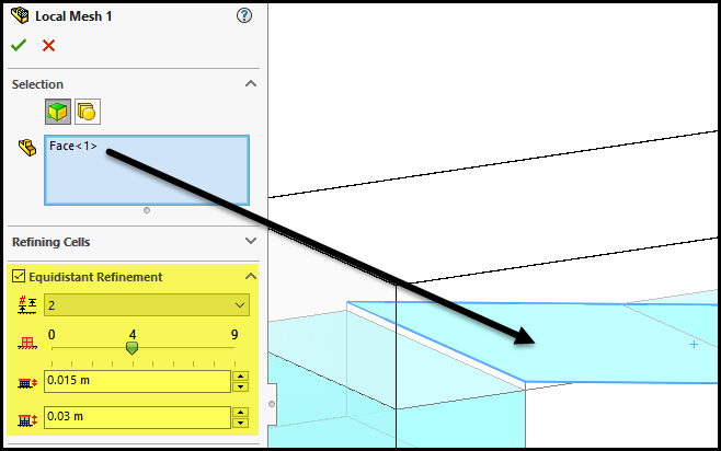
The first is an “equidistant refinement” control referencing the ramp face:
The second applies refinement to a cuboid region of the pool where we expect the free surface to be established:
The third is another “equidistant refinement” referencing faces at the far end of the channel:
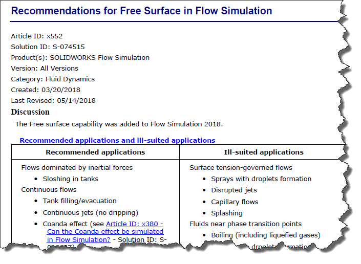
Please see Solution ID S-074515 in the Knowledge Base section of the SOLIDWORKS Customer Portal for these and other free surface recommendations.
We’re always learning and growing our knowledge of the validation tools and I’m excited to pass along what I’ve learned about this great feature in SOLIDWORKS Flow Simulation! Thanks for reading this blog.
Kurt Kurtin
Sr. Product Manager, Simulation
Computer Aided Technology, Inc.