3D Scanning, Reverse Engineering in SOLIDWORKS, and 3D Printing a Buckle Clip
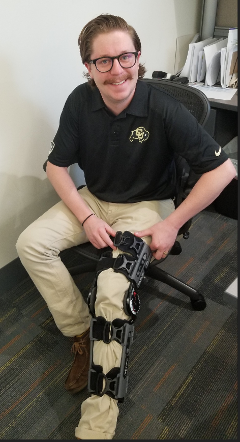
Meet Rob, Rob has a leg brace, but one of the buckles broke. Poor Rob.
Lets make a new clip for Rob!
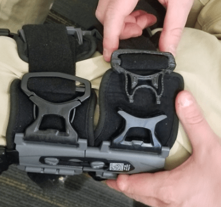
How are we going to go about reverse engineering this fairly complex clip design? We could use the old caliper method, but it might be hard to get some of the angles right and it would take a while. Lets see what else we have on hand around the office. We can get accurate measurements from one of the non-broken clips by scanning it with a Creaform Handyscan 700. We can use SOLIDWORKS to create the CAD model and then we will be able to print up the model on one of our Stratasys 3D Printers.
First step is to scan the buckle with the Creaform scanner. We won’t just reprint the clip exactly from the scan, which is an option, but we will use the scan data as a design template to model up a new clip in SOLIDWORKS. The problem with simply printing the direct scan data is that it is not a parametric model, so if we want to add anything new, change any diameters or thicknesses, we can’t very easily.
The scanning only took about 2 minutes to get all of the data we need, not a perfect scan but we don’t need one for this purpose. Now we just have to extract the relevant geometries from the mesh to bring over into SOLIDWORKS, which the Creaform Software, VXelements, has a direct API for.
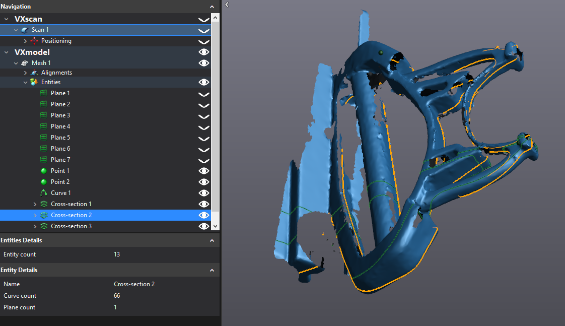
Now with the click of a button I can transfer the Cross-sections of the model, Planes, Points, and even the entire mesh directly over into a SOLIDWORKS part file. Once we get this ‘design template’ into SOLIDWORKS we can now start to make our own dimensioned sketches off of the provided data.
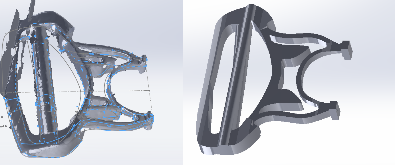
After a few extrudes and cuts we have a fully parametric SOLIDWORKS model ready to be printed or modified as needed. Now we can open the SOLIDWORKS file up directly in GrabCad Print to do all of the layer processing and support generation for us, no longer do we have to worry about translating the CAD file into an STL file and making sure the resolution is high enough as an intermediate step.
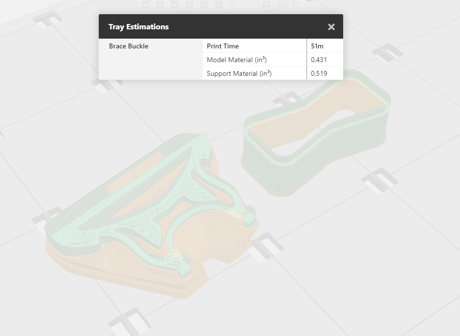
Print the buckle and go test it out on Rob’s leg brace and he is as good as new! The entire process took about an hour and half. It took about thirty minutes to scan and remodel the clip up in SOLIDWORKS, and, as we can see from the estimate above, about 50 minutes to additive manufacture (3D Print) it.
Go get em Rob!
Tim Crennen
Applications Engineer, 3D Printing and 3D Scanning
Computer Aided Technology, Inc