A Beginner’s Look at SOLIDWORKS SimulationXpress. Part One
I’m guessing if you’re here you’ve probably heard about this amazing tool hiding inside every SOLIDWORKS package. SimulationXpress focuses on simplicity making it a great introduction to simulation. The step by step wizard guides you through the process and does not require you to be an expert in design validation or Finite Element Analysis (FEA). Plus, it’s free! Being new to the world of simulation myself, I found this tool so easy to learn I kicked myself for not taking advantage of it sooner! Today we’re going to cover the steps needed to successfully set up a simulation study. In part two, we will cover running the study, reading the results and optimizing the design.
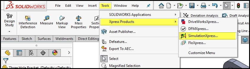
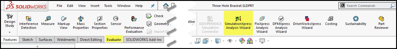
To start your simulation, go to Tools > Xpress Products > SimulationXpress… or on the Evaluate Toolbar. Still don’t see it? Make sure you have a part file open as SimulationXpress is not supported for assemblies.
If this is your first time launching SimulationXpress you will need to enter a product code to activate the tool. Just follow the steps outlined here, and in about five minutes you’ll have your very own code!
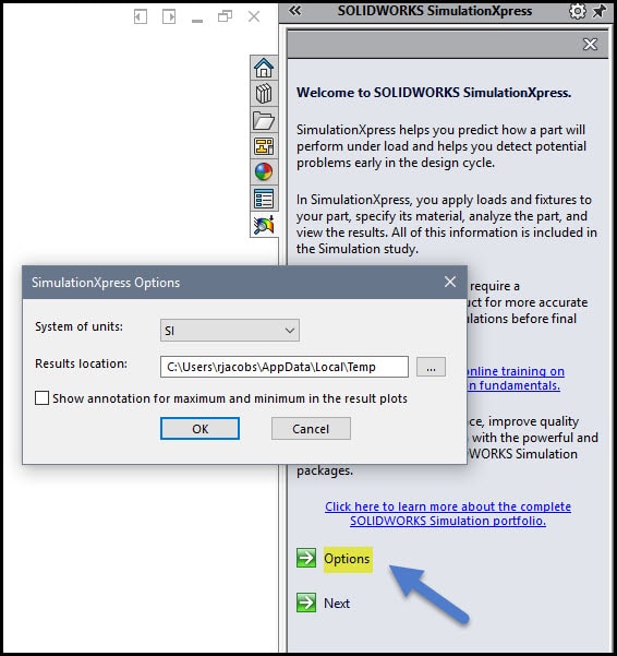
Clicking the first green arrow opens the Options dialog box. Using the drop-down menu, you can select either SI or English as the system of units for this simulation. These units are independent of the units set within your part file and can be changed, if needed, after the study. The results location allows you to define the location where you want your results stored and the bottom checkbox allows you to turn the annotations in the result plots on or off (more on this later).
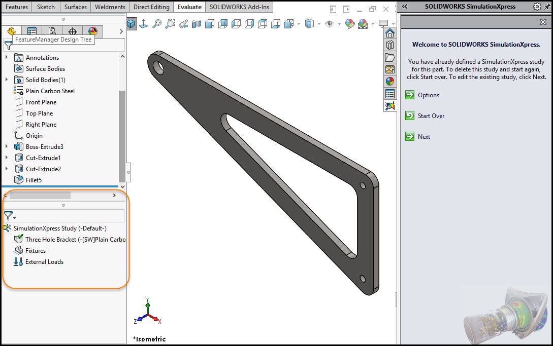
After clicking ‘Next’ to continue, you’ll notice the FeatureManager is split and a simulation study has been added in the lower portion. Eventually, this will also house the results of the analysis, the fixtures, loads and meshes. You can add/modify the features here but for the rest of this blog, we’re going to focus on utilizing the wizard in the task pane. Click the green arrow by “Next” to continue.
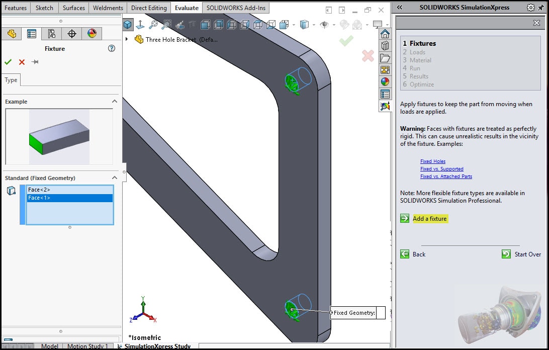
1. Fixtures
Defining a fixture allows us to tell the software what is going to be held in place when loads are applied. More advanced simulation programs allow for a variety of fixture types, in SimulationXpress we are only allowed fixed fixtures. While treating every face as perfectly rigid can lead to some unrealistic results, SimulationXpress can help you identify areas of high stress and give you a good idea of how your part will deform.
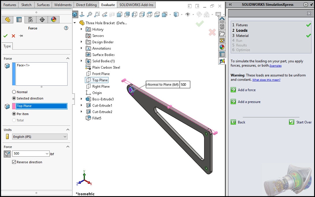
2. Loads
In keeping with the simplistic theme, SimulationXpress assumes that all loads are both uniform and constant. That means they are applied slowly and gradually until they reach their full magnitudes. After reaching their full magnitudes the loads will remain constant. If you wish to simulate conditions such as vibrations, fatigue or shock loading you will need the more advanced capabilities of SOLIDWORKS Simulation.
When applying an external load to a part you have the choice of applying force, pressure or a combination of both.
Applying pressure is as easy as selecting a single face or multiple faces, determining if that pressure should be applied normal to the selected face or in the direction of a selected reference plane. Select the pressure units, then enter the pressure value and click the green check mark.
Applying a force is similar to applying a pressure except you can control how the force is distributed. Forces can be distributed in two ways, evenly across the selected faces or applied to each individual face. Meaning if you apply 3000 newtons total and have two faces selected, each face will receive a force of 1500 newtons. If you apply 3000 newtons per item and have those same two faces selected then you will be applying a total force of 6000 newtons.
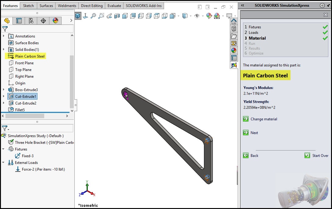
3. Material
In simulation studies, the response of a part depends on the material assigned to the part. Since SOLIDWORKS shares your material library, including custom materials, with SimulationXpress if your part already has a material assigned, you won’t have to do anything! The material can be set independent of the model but keep in mind SimulationXpress is great for ductile materials such as copper, aluminum and steel. If your design requires non-linear material such as rubber or brittle material used in most ceramics, you will need to use the more complete analysis tools in SOLIDWORKS Simulation.
Thank you for taking the time to check out SimulationXpress. If you found this interesting be sure come back for part two where we will run the simulation, analyze the results and optimize our design!
Rhonda Jacobs
Application Engineer
Computer Aided Technology, LLC