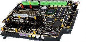
SOLIDWORKS PCB: A New Way to Design Printed Circuit Boards
 Understanding the lay of the land is extremely important when mechanical and electrical engineers are working on a design. Even when using the same CAD system, a back and forth disconnected process can leave room for error and create major setbacks.
Many engineers experience the headache of having significant changes made in a design and feeling like they have to start from scratch. Even simple changes in a design can completely alter the routing of circuits and connectors in a PCB.
If you’ve ever found yourself in this scenario, help is a click away. You can now use SOLIDWORKS PCB, powered by Altium. This intuitive software will help eliminate your frustrations associated with changes in circuit board design.
SOLIDWORKS PCB makes everyone a team player
Everyone needs to get along, but when trying to communicate between ECAD  and MCAD tools, details can get lost or overlooked along the way causing frustration. This back and forth communication between mechanical and electrical engineers costs companies a lot of time and money.
How can PCB help with communication? When a design is passed back and forth in different file formats, engineers have to keep track of what changes have been made. SOLIDWORKS PCB allows ECAD and MCAD software to communicate with each other – without the file transfer.
When a change is made in SOLIDWORKS PCB, behind the scenes those same changes are being updated in SOLIDWORKS in real time and vice versa. Users no longer have to jump around between files to ensure everyone is on the same page.
SOLIDWORKS PCB offers a helping hand
Whether a major redesign needs to take place or a slight adjustment, PCB has your back. Among countless capabilities lies an interactive routing tool, which assists in choosing the best routing options depending on your design constraints.
How can PCB eliminate mistakes? Easily customizable Design Rule Checks (DRC) are built right into the design flow to ensure Schematics and PCBs are laid out error free and to allow for reliable and affordable manufacturing, eliminating the need for a redesign down the road.
Component Supplier data is also listed in a real-time database with cost and availability information, saving time and offering an even more valuable experience.
There is also an Altium Connector
If you have SOLIDWORKS for your Mechanical CAD needs, and are using Altium Designer for your PCB design already, you’re in luck! The SOLIDWORKS Altium Connector allows you to communicate smoothly between mechanical and electrical designs the same way as described above.
With the PCB connector, design changes are made interchangeably between SOLIDWORKS and Altium Designer in a synced communication – without having to learn a new design program – and allowing you to retain and enhance the value of your Altium investment.
It’s time to start thinking of new ways to become more productive and collaborate seamlessly among designers. Adding SOLIDWORKS PCB to your workflow lets you keep up with demand and respond to changes with a solid solution.
Images Courtesy of: SOLIDWORKS