A Real-World Example of Re-engineering and Customization
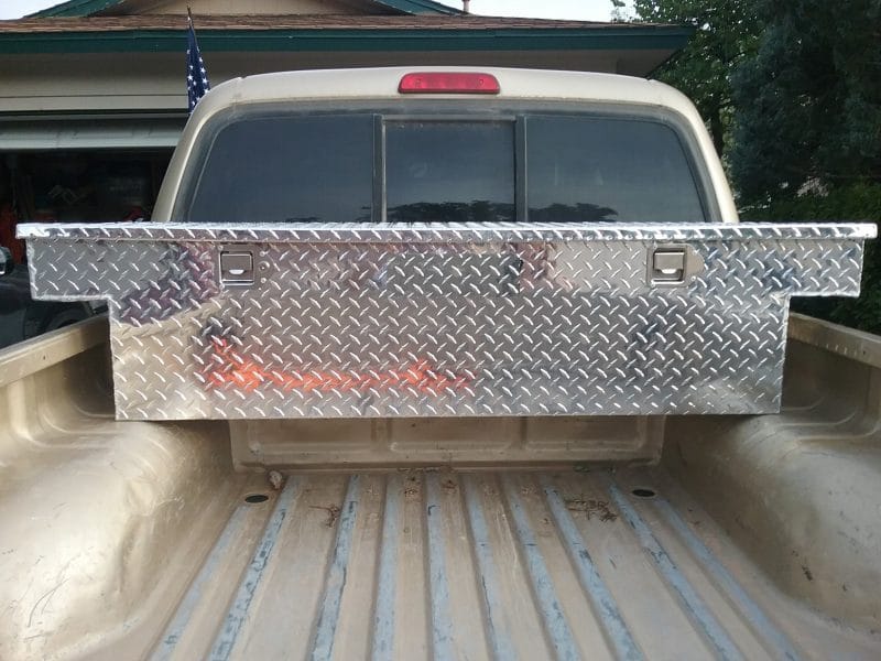
I recently purchased a cross-over toolbox for my small truck. I was very careful to check with the vendors to make sure that the toolbox would fit into my year/make/model of truck and that I was getting the best price. Well, my toolbox arrived and guess what? It does not fit properly in the bed of my truck. I made the foolish mistake of not getting the critical measurement from my truck bed and comparing them to the manufacturer’s specifications for the toolbox.
I contacted the company I had purchased the product from, and they said they would happily refund my purchase price if I sent the unit back and paid the shipping. I had no idea that shipping something that big would cost me more than half the purchase price. So, I decided that I would modify the unit to fit my truck.
Hopefully in this picture, you can see that the bottom portion of the toolbox is too wide to fit between my wheel wells.
Here is where SOLIDWORKS and CREAFORM come into the picture.
First I enlisted the help of our Manufacturing Specialist Collin Manchester to scan the bed of my truck with the Go!SCAN 3D, a hand-held white light 3D scanner.
Since my requirements are simple, I just asked him to create a cross-section of the truck bed from the surfaces he was creating and give it to me as a SOLIDWORKS part. Here is the part.
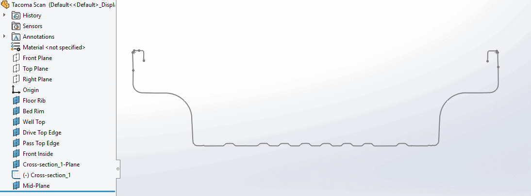
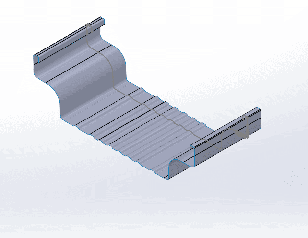
The first thing I needed to do with this drawing was to extrude it into a surface to show the contour of the truck bed.
The next step is to offset this surface so I have some room for the fit. .25” should be enough.
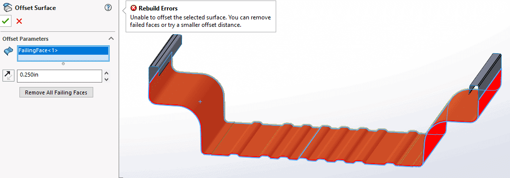
I got an error indicating that the surface is either too complex or has inconsistencies that prevent the offset from happening. One option is to use the sketch to create a duplicate that is simpler. I created a new sketch on the same plane as the cross section and converted the spline to the new sketch. When I removed the on-edge constraints I can see why there was a problem with this surface.
The reason the line looks so thick is because there 3,108 spline points. This is probably why the surface is so complicated.
The simpler way to do this is use the original spline and create something simpler with lines and curves using the spline as a guide. I then was able to offset the sketch that .25”.
Now I can use the offset sketch to create a new surface.
Now that I have the correct shape for my modified toolbox the next step is to take the specification of the toolbox and create a simple solid model.
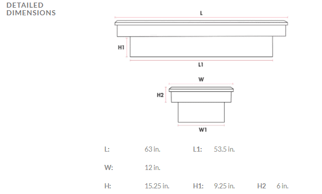
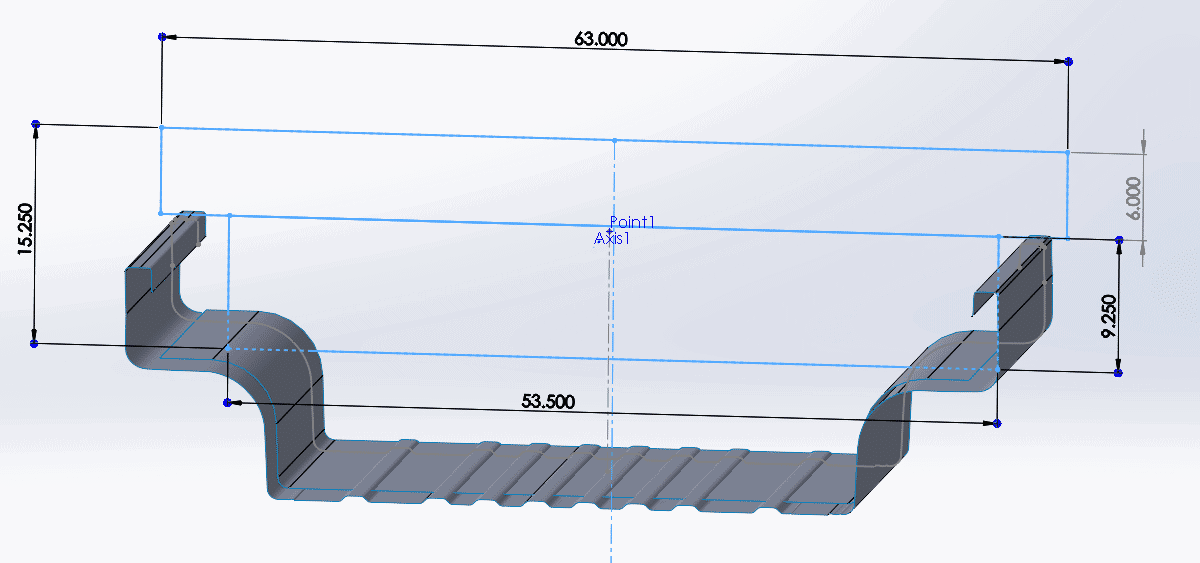
Here is the specification of the toolbox from the manufacturer.
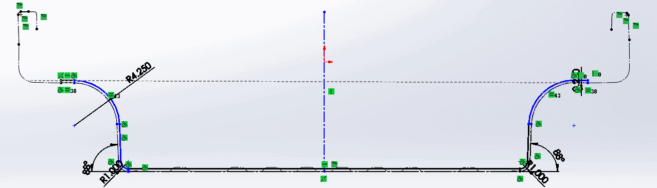
This is the sketch for the toolbox.
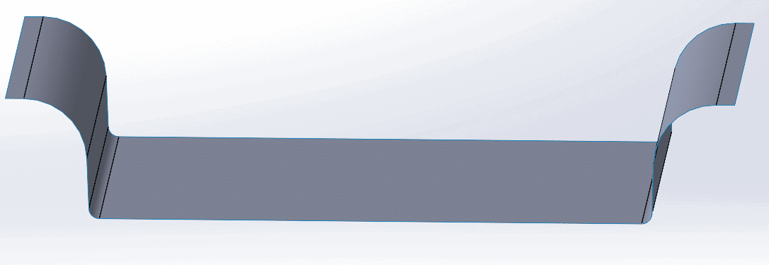
Next, I will create the extrude for the toolbox model.
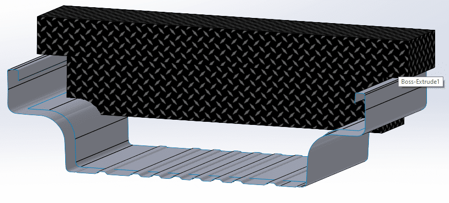
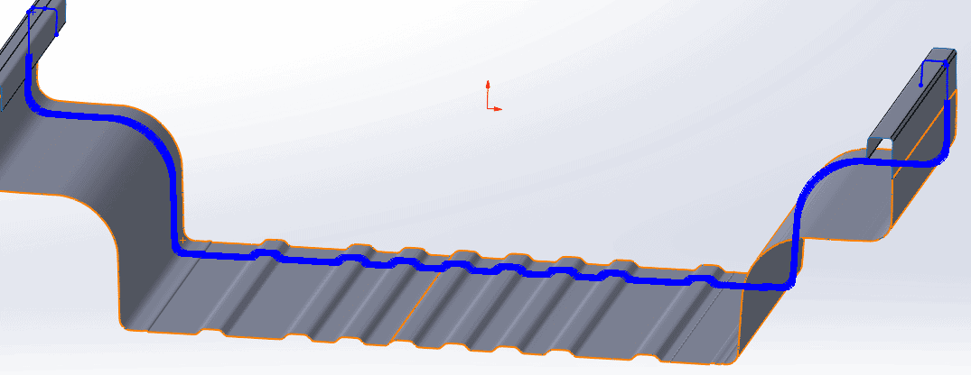
By using the “Cut With Surface” Feature I can remove the portions that overlap the surface.
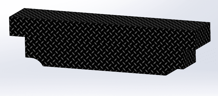
This is what the finished toolbox will look like (mostly).
Lastly, I will need to evaluate if there will be enough material to make the changes. I can do it on one side, and it will work for the other side as well.
Using the measure tool, I will determine how much of the corner I will be making available.
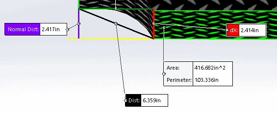
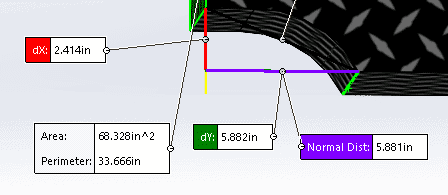
So, it looks like I will have (2.417 + 5.882 = 8.299) length of material. I will need to measure the arc length of the new surface to see if I have enough material.
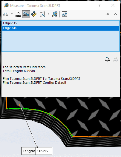
The arc length came back 6.795”, so It looks like I’ll have about 1.5” of extra material I will need to cut off.
Now I just need to hope my sheet metal and welding skills are as good as my SOLIDWORKS skills.
Dennis Barnes
Application Engineer, Software Support
Computer Aided Technology, Inc.